
User Manual


pg. 12
Copyright © 2017- www.SingleTact.com
2.4.2 I
2
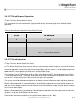
C Read Request Operation
I
2
C bus Transfer: Master Write to Slave.
This command sets the read location (register block offset) and read length for a following Read
operation.
Table 4 Read Request Operation Data Packet Format
BYTE
TO SENSOR
0
0x01
1
Read offset in register block
2
Number or bytes to read (1 – 32)
3
0xFF – end of packet delimiter
2.4.3 I
2
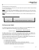
C Read Operation
I
2
C bus Transfer: Master Read from Slave.
An I
2
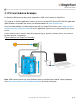
C Master Read from Slave transfer can be used to directly read the register set and sensor data.
In normal operation a read of the two Sensor Output byte registers returns a 10-bit output range from
0000 to 0x3FF, corresponding to the 0 to 2V analog output range.
The functional sensor FSR output range is 9-bits from x0100 to 0x2FF, corresponding to the 0.5V to
1.5V analog output range. The larger 10-bit total range allows for detection of negative values when
the sensor is under tension and some level of over pressure detection.
The sensor should be unloaded at power on to allow the sensor’s baseline to be registered correctly.
Where a Read operation is not preceded by a Read Request operation the read location defaults to
128 (the sensor output location) and consecutive reads will therefore simply read the default 32 bytes
of the sensor data region.
Where a Read operating is preceded by a Read Request operation then the register offset and read
length as set by the Read Request will be used.
Data can be read from anywhere in the register block (addresses 0 – 191).