
Specifications


RFC-1 Programming Examples page 7.6
7.6 Alarm Limits—Status Channel
In this example we will program Alarm B to monitor telemetry channel 05 for the loss of voltage on a status channel.
The alarm will have an upper limit of “9999” and a lower limit of “0500”. This might be the case if an audio failsafe is
monitoring presence of an audio signal. The output of the failsafe is connected so that 5 volts DC is applied to the
telemetry input when audio is present and 0 volts DC is applied when audio fails.
In this case the upper limit is not needed. The upper limit 9999 is used because it is so high it will never be able to
trip this alarm. The lower limit does the work in this example but the value is not critical—any value from 0100 to
1000 would work.
When the channel reading goes from “status on” to “status off”, the equivalent analog reading goes from above 2000
to 0. The midpoint of that range (~1000) is where the status reading actually changes. So the value 0500 is selected
because it is below the trip point and large enough so that it must be crossed as the analog data drops to 0000.
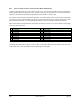
1. Enter the advanced programming mode: 80
2. Enter the advanced programming security code: 4150
3. Enter the starting address from the address table for alarm B: 0864
4. Enter the first digit of the telemetry channel to be monitored: 0
5. Press the # key to write this value and increment to the next address in memory
6. Enter the second digit of the telemetry channel to be monitored: 5
7. Press the # key to write this value and increment to the next address in memory
8. From Section 6, enter the number of the trigger rule: 7 (lower limit crossing only, 5 also works)
9. Press the # key to enter this value and increment to the next address in memory
10. Enter the number of the action sequence that should be triggered: 9 (place telephone calls)
11. Press the # key to enter this value and increment to the next address in memory
12. Enter the first digit of the upper limit: 9
13. Press the # key to write this value and increment to the next address in memory
14. Enter the second digit of the upper limit: 9
15. Press the # key to write this value and increment to the next address in memory
16. Enter the third digit of the upper limit: 9
17. Press the # key to write this value and increment to the next address in memory
18. Enter the fourth digit of the upper limit: 9
19. Press the # key to write this value and increment to the next address in memory
20. Enter the first digit of the lower limit: 0
21. Press the # key to write this value and increment to the next address in memory
22. Enter the second digit of the lower limit: 5
23. Press the # key to write this value and increment to the next address in memory
24. Enter the third digit of the lower limit: 0
25. Press the # key to write this value and increment to the next address in memory
26. Enter the fourth digit of the lower limit: 0
27. Press the # key to write this value and increment to the next address in memory
28. Press the ❊ key to exit the programming mode
The reverse of this alarm would trigger when 5 volts DC is applied and the channel reading is “status on”. The alarm
limits would be “1500” for the upper limit, “0000” for the lower limit and either trigger rule 5 or 6 would work.
The telemetry channel requires no special programming—it uses the auto-status feature of the RFC-1. The channel
is calibrated so that it reads “status on” when the voltage is applied and “status off” when the voltage is removed.