
Installation manual


TransceiverUnitassembly
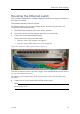
Figure31Powercablesconnectedtothe
terminalboard(example)
Thesecablesareconnectedfortestpurposes
whenthesidewallofthetransceivercabinet
hasbeenremoved.
1Connecteachofthepower
cablestothethreeterminal
boardsintheTransceiverUnit.
•Thetopterminalboardis
usedtoacceptthepower
cablesfromPowerSupply
Unitno.0.Thepoweristhen
connectedtoTRXUno.0.
•Thebottomrearterminal
boardisusedtoacceptthe
powercablesfromPower
SupplyUnitno.1.Thepower
isthenconnectedtoTRXU
no.1.
•Thebottomforwardterminal
boardisusedtoacceptthe
powercablesfromPower
SupplyUnitno.2.Thepower
isthenconnectedtoTRXU
no.2.
→PowerSupplyUnitsDC
outputwiringonpage138
2Securethecablestotheframeinthecabinetusingwirewraps.
331549/B
77