
Specifications


8 | Installation
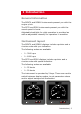
Cable connection and interface
Signal input, network and power supply are wired to the
enclosed terminal block that is to be plugged in on the
rear side.
The instrument is delivered with a 0.3 m SimNet cable
with a standard SimNet plug in both ends. One plug
must be cut off and the wires connected to terminals 3
through 6 according to the color codes shown below.
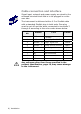
TERMINAL
NO
SIGNAL TYPE COLOR
1 GND
- Supply
-
2 VCC + Supply 12 - 24V DC -
3 SimNet - H “High” signal line Yellow
4 SimNet - C Power source common Black
5 SimNet - L “Low” signal line Blue
6 SimNet - S Power source positive Red
7 NC Not connected -
8 NC Not connected -
9 NC Not connected -
Any voltages other than those specied in the
product specication, page 19, may cause damage
to the instrument.
1