
Specifications


Installation
20220752J 25
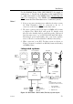
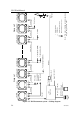
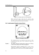
An example of a fully equipped IS 15 system is shown in Figure
5-5. See also the Interconnection – Principle diagram Figure 6-5
in the IS15 General Manual.
Choosing the Cable Routes
When routing the cables choose the most direct paths while
avoiding the following hazards:
• Sharp bends or kinks in the cable
• Hot surfaces (exhaust manifolds or cooking equipment)
• Rotating or reciprocating equipment
• Sharp or abrasive surfaces
• Door and window jambs
• Corrosive fluids or gases
Extending Cables
Refer to page 6 for information.
Note ! The total length of (Roblink) cables in a system should not
exceed 30 m not
including the cable to the Wind Transducer.
Refer to section 6.6 in IS15 General Manual.
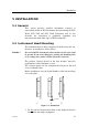
Securing the Cables
After the ideal cable routing has been established, use tie-wraps,
‘P’ - clips or other fixings to secure the cables along the routings.
Note ! To prevent chafing add protection for the cable jackets where the
cables pass through bulkheads, or past sharp edges.
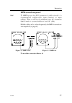
Secure the cable near to the terminals for strain relieving. See
also Figure 5-6 below.
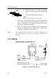
Secure the cable ends with enough slack to allow for easy
connection / disconnection with the instrument removed from its
location.
Cut any spare wire ends to an appropriate length.
Securing the connectors
For extra security fasten the connectors with the enclosed self-
tapping screws.