
Specifications
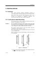


Installation
20220752J 23
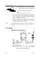
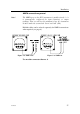
Use the Roblink Power Cable (P/N 22093587) for supply to
connector no. 1. Cut off one of the plugs on the supplied 0,3 m
(1’) cable and extend it to the NMEA source using twisted pair
cable. Use connector no. 4 for NMEA connection (see Figure
5-9). Connect the Wind Transducer to no. 3 connector (sensor).
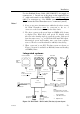
Notes !
1. If one or two more instruments are added to the above system
the Wind Transducer must
be connected to the no. 2
connector on the last instrument in the daisy chain.
2. The above system needs speed input on NMEA 0183 format
to display True Wind angle and speed. To display wind
direction also heading input is required together with speed
from the same source, e.g. a GPS with SOG and COG output.
Alternatively speed and heading may come from separate
sources. Then a second head must be added for interfacing.
3. When connected to an IS15 Tri-data system as shown on
Figure 5-4 speed is available on Roblink format and heading
on NMEA format.
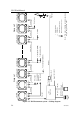
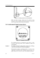
Integrated systems
Speed/temp
transducer
Depth
transducer
Supply 10,8-15,6VDC
SIMRAD
IS15 Combi/Multi
10 m (33')
10 m (33')
10 m (33')
IS15
Transceiver
SIMRAD
0,3 m (1')
IS15 Combi/Multi
Wind
Transducer
IS15 Wind
SIMRAD
Junction box (mast foot)
0,3 m (1')
10 m (33') 30 m (99')
From Autopilot
(NMEA)
Stand alone
compass
NMEA
To Autopilot
(NMEA)
NOTE:
The wind transducer should be
connected to the Transceiver unit.
NOTE:
Cables are
not shown
in connected order.
Circuit breaker
Optional
third
instrument
*
*
*
*
**
**
Denotes Roblink
cable with connector
Optional extra
*
**
Figure 5-4 IS15 Wind – IS15 Combi (Tri-data) System layout