
Specifications


Installation
20220760L 73
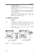
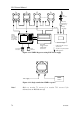
6.9 IS15 Transceiver
This unit contains the depth and the speed/temperature
electronics. The power supply (battery) and the transducers are
connected to the unit.
The unit has three Roblink connectors for instrument heads and
wind transducer.
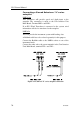
Speed/temp transducer and depth transducer are hard-wired to
plug-in screw terminals on the PCB (pwr terminal is fixed).
• Remove the top cover to get access to the plug-in terminals.
• Press the cable end through an appropriate recess in the
gasket (ref. to Figure 6-5). Remove about 2 cm (0.8”) of the
cable insulation.
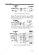
• Pull out the plug-in terminal before connecting the wires.
• Be careful to prepare all wires on each cable before putting it
through the gasket to avoid strands getting onto the PCB.
• Insulate the shields by electrical tape or similar.
• Make the connections according to the following connection
diagrams.
• Leave sufficient free wires so that the plug-in terminals can
be easily connected/disconnected.
• Ensure that no strands are left inside the unit before
putting on the cover.
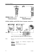
Figure 6-16 IS15 Transceiver PCB - Connector and terminal
location