
Specifications


IS15 General Manual
62 20220760L
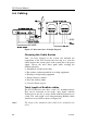
1. Do not
remove the protection film on the display before the
installation and setup is completed.
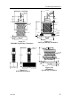
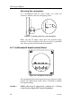
2. Carefully position the self-adhesive template provided on the
surface where the display head is to be mounted.
3. Allow sufficient space for the protection cover as shown on
the template when instruments are installed adjacent to each
other.
4. Drill a small pilot hole first, and then check the location on the
other side of the panel or bulkhead to confirm suitability.
5. Open out the pilot hole to 85 mm (3.4”) using a cutter in a
hand-held brace, or an electric drill saw (86 mm or 3 3/8”).
6. Drill the four screw holes using a 2.5 mm (0.1”) drill.
7. Secure the instrument using the four self-tapping screws
provided. Ensure that the sealing gasket is correctly located.
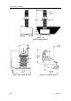
8. Apply the front panel corners.
Note ! Ensure that all sockets without cable connections have the
protection plug inserted.
Caution ! Do not over-tighten fixing screws.
Do not use sealing compound on the instrument back.
Do not use WD40 or any solvent on any part of the
instrument.
Figure 6-2 - Mounting Details (Not To Scale)