
User's Manual Part 2


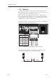

12.2.6 Summary
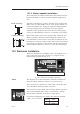
Summary of the RS81/82 connections –
Instruction manual
101
E04572
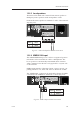
12.2.7 Cable strain relief
Once all the cables have been run to the appropriate peripher-
als and connected to the transceiver unit they should be
secured to ensure that they are not snagged or exposed to
excess strain.
Screw the strain relief tab to the cable exit port on the trans-
ceiver unit using the screws supplied and secure the cables to
the tab using the wraps as shown (Fig 12.9):
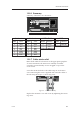
STANDARD CONNECTIONS
Terminal
Number
1
2
3
4
5
6
7
8
Wire
Colour
Brown
Green
Red
White
Blue
Yellow
Orange
Black
Station 1
Terminal
Number
1
2
3
4
5
6
7
8
Wire
Colour
Brown
Green
Red
White
Blue
Yellow
Orange
Black
Station 2
Terminal
Number
1
2
3
4
Wire
Reference
Common In -
Data In +
iDSC -
iDSC +
NMEA/iDSC
Terminal
Number
+
-
Wire
Reference
Red (12v in)
Black (0v)
PWR
Fig 12.9 - Cable strain relief
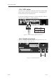
Replace the terminal cover and secure by tightening the retain-
ing screw.