
User's Manual Part 2


Instruction manual
97
E04572
12.1.3 Station speaker installation
The loudspeaker should be installed near the handset and can
be flush-mounted or surface mounted with the supplied pat-
tress.
Flush mounting Attach the self-adhesive gasket to the back of the loudspeaker.
Remove the four detachable corners of the speaker which con-
ceal the mounting holes. Apply the supplied cutting template
to the mounting position. Carefully cut out the aperture
required for the speaker back and use the short self-tapping
screws provided. Refit the corners to conceal the screw fixings.
Surface mounting Drill a 5mm (0.2in) hole for the speaker cable. Attach the self-
adhesive gasket to the back of the loudspeaker. Remove the
four detachable corners which conceal the mounting holes. Fit
the pattress to the back of the speaker and use the long self-tap-
ping screws provided to fix the speaker and the pattress block
to the bulkhead. Refit the corners to conceal the screw fixings.
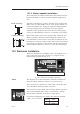
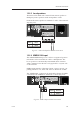
12.2 Electronic installation
Electronic installation is straightforward – all peripherals con-
nect to the transceiver unit (“black box”) using the clearly
labelled plug-in terminals (Fig 12.2).
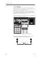
Fig 12.2 - Transceiver terminal connections
STANDARD CONNECTIONS
NOTE The diagram shows the terminal bay with the standard con-
nections and the SimNet connectors (see section 12.2.5).
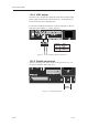
If it is necessary to shorten any of the cables, ensure the ends
are re-tinned for the best quality connection.
The transceiver unit is fitted with a 10Amp “blade”-type fuse.
It is recommended that the radio is connected to a 10Amp
fused switch or breaker on the boat’s switch panel.
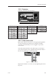
Connect the supplied power cable to the terminals marked
PWR + and - as follows:
Terminal
Number
1
2
Wire
Colour
Red
Black