
Installation manual

Transducer installation
33
851-165187 / Rev.A
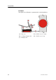
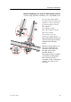
Box keel
Vessels with a box keel may use this for transducer installation.
The box keel is already the deepest part of the vessel. If the box
keel is too narrow to accommodate the transducer, it can be
widened, either symmetrically or to one side only. In the last
case the installation could also be described as a blister m erged
into the keel.
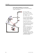
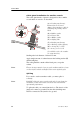
Mounting and clamping rings
Circular transducers may be provided with mounting a nd
clamping rings, or with drawings to allow for local production
of these. The mounting ring is welded to the hole in the box
keel, while the clamping ring f its around the edge of the
transducer body. Bolts through the clamping ring into the
mounting ring will then secure the t ransducer between them.
Note that several transducers use direction guides to allow
correct mounting.
Inclination of the transducer face
If possible, incline the transducer face approximately 1-2
degrees, so t hat the flowing water meets it directly. This assures
laminar water flow.
Smooth surface
Mounting screws or bolts must not be extruding from the box
keel. Ensure t hat the surface of the transducer face, the box, the
hull plating and putty around the transducer is as even and
smooth as possible. Obstructions on these surfaces will create
problems with turbulant flow.
Horizontal support bar
Large diameter transducers must be fitted with a horizontal
support bar. This bar can be secured to the mounting ring using
threaded rods.