
Installation manual


Simrad PI54
30
851-165187 / Rev.A
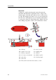
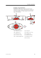
Example: Small transducer
The illustration below shows a typical transducer blister
designed for a small transducer. The same blister design
principles as for a large transducer apply.
(A) = Streamlined blister (E) = Air outlet
(B) = Mounting ring (F) = Forward
(C) = Clamping ring (G) = Tr ansducer cable
(D) = Guide
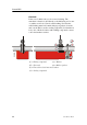
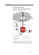
Note that the transducer cable must be provided with a cable
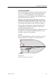
loop inside the blister. Observe the vertical forward edge of the
blister. This will guide the water to each side of the blister.