
Installation manual


Transducer installation
29
851-165187 / Rev.A
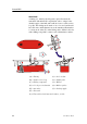
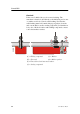
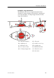
Example: Large transducer
The illustration below shows a typical transducer blister
designed for a large transducer. Note that due to the physical
size of the transducer, a U-shaped support bar (E) is used to
support the transducer.
(A) = St reamlined blister (F) = Forward
(B) = Stiffening rib (G) = Cable service loop
(C) = Drainage holes (H) = St uffing t ube
(D) = 1-2 degrees angle (I) = Minimum 400 mm
(E) = U-shaped support bar (J) = Rounded corners
(K) = Air outlet