
Installation manual

24 | Wiring the radar system
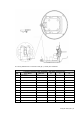
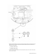
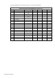
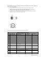
The wiring details for the connector ends (B, C, D, and E) are as follows:
4 kW interconnection cable (NS00310X) connector ends
Pin Color/Name AWG size B C D E
1 Blue (thick)
#16
1
2 Purple (thick)
#16
1
3 Red (thick)
#16
2
4 Yellow (thick)
#16
2
5 Drain wire (Coax line)
#24 2
6 No connection
7 No connection
8 No connection
9 Yellow (thin)
#24 twist pair 3
10 Clear Coax line
#24 1
11 No connection
12 Green (thin)
#24
5
13 White (thin)
#24 twist pair 4
14 Drain wire
#24
2
15 Shield line
#24
1
16 Orange (medium)
#18
3
Shell Braid shield
X