Reference manual Simrad SH90 Fish finding sonar www.simrad.
Simrad SH90 Reference manual This manual provides you with reference information required to operate and fully understand the commands, menus, operational modes and options provided by the Simrad SH90. For user information in brief, refer to the Simrad SH90 Operator manual. WARNING: The Simrad SH90 sonar must never be powered up when the ship is in dry dock. The transducer will be damaged if it transmits in open air.
Document history Document no: 323775 / Revisjon: B / ISBN: 978-82-8066-124-1 Rev.A 10.05.2010 First release. Released for SW 2.1.X. Rev.B 20.08.2010 New procedures for software backup and restore. See Software procedures on page 60. Copyright ©2010 Kongsberg Maritime AS The information contained in this document remains the sole property of Kongsberg Maritime AS.
Reference manual Table of contents ABOUT THIS MANUAL ..................................................... 11 SIMRAD SH90 ................................................................. 12 Important matters ...................................................................................................12 Basic information ...................................................................................................13 Main units......................................................................
Simrad SH90 How to hide the menu ................................................................................. 40 How to simplify the menu ........................................................................... 40 Gain adjustment procedures ...................................................................................41 How to adjust the gain................................................................................. 41 How to adjust the AGC ..............................................
Reference manual Software procedures ...............................................................................................60 Backup and restore ..................................................................................... 60 How to create a backup image using the ’Norton Ghost 8’ utility ................... 60 How to restore from a backup image using the ’Norton Ghost 8’ utility........... 61 How to reactivate the Windows licence ........................................................
Simrad SH90 System Test menu ..................................................................................... 105 Sort Modes menu...................................................................................... 107 Pop-up menus .......................................................................................................107 View pop-up menu.................................................................................... 108 Catch View pop-up menu .....................................
Reference manual Inspect Object........................................................................................... 140 Language ................................................................................................. 141 Menu ....................................................................................................... 142 Message Bar............................................................................................. 142 Middle Pos(ition)..................................
Simrad SH90 Zoom ....................................................................................................... 176 Zoom Scale .............................................................................................. 177 BASIC THEORY.............................................................. 178 Settings .................................................................................................................178 What is TVG? .........................................................
Reference manual Hull unit familiarization ............................................................................ 195 Motor Control Unit familiarization............................................................. 196 Fuses in the Motor Control Unit................................................................. 197 Hoisting and lowering from the sonar room ................................................ 198 Motor protecting switch (S301) ............................................................
Simrad SH90 10 323775/B
About this manual ABOUT THIS MANUAL Purpose The purpose of this reference manual is to provide the descriptions, procedures and detailed parameter explanations required to allow for safe and efficient use of the Simrad SH90, as well as a thorough understanding of the system parameters and adjustments. A good understanding of system functions and controls is essential to fully take advantage of the functionality provided.
Simrad SH90 SIMRAD SH90 Study this chapter to familiarize yourself with the Simrad SH90. Topics • Important matters on page 12 • Basic information on page 13 • Main units on page 14 • System diagram on page 17 • Basic functionality on page 17 • Optional functionality on page 21 • Peripheral equipment on page 22 • Support information on page 23 Important matters As with all advanced instruments, there are a few important matters about the SH90 that you must remember.
Simrad SH90 Manual operation of the hull unit In the event of improper operation, the powerful 3 kW electric motor may cause serious damage to the equipment and/or injury to personnel. Therefore, before you start the operation, read carefully through the relevant procedure(s). You will then familiarize yourself with the method . If something breaks down If you think that something has been damaged on the sonar, contact your local dealer for advice.
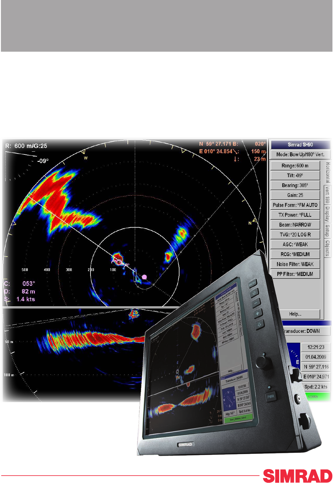
Simrad SH90 Main units The Simrad SH90 comprises the following units: Normally installed in the wheelhouse: • Display Unit • Operating Panel • Processor Unit • Operating Panel power supply Normally installed in the sonar room: • Transceiver Unit • Power Supply Unit • Hull Unit Wheelhouse units Display Unit The colour display is a high-resolution monitor. In addition to the sonar picture, the monitor will also display the menu system for the interactive operation.
Simrad SH90 The computer is based on a commercial design, but the software and hardware has been specified and assembled by Simrad to suit the SH90 requirements. The computer holds a DVD player for use with future software upgrades. Figure 2 Processor Unit The purpose of this computer is to allow you to control the sonar. The computer serves several functions. • It controls the overall operation of the sonar functions. • It provides the graphic presentation of the sonar modes and echoes.
Simrad SH90 Unit in the wheelhouse, and a second Ethernet cable is used to control the hull unit. The third Ethernet cable connects to the Power Supply Unit. The transducer cables from the hull unit are plugged into the side wall of the Transceiver Unit cabinet using a special plug. The Transceiver Unit is mounted on the bulkhead using powerful shock absorbers. The connectors for power and interface are located at the bottom of the cabinet.
Simrad SH90 System diagram Figure 3 A SH90 Simplified system diagram Processor Unit SIMRAD B B Display Unit C Operating Panel D Operating Panel power supply E Transceiver Unit F Power Supply Unit G Motor Control Unit H Hull Unit I Transducer MENU PWR A SIMRAD SX90 SIMRAD C D G H F I (CD015041-001) E Basic functionality The basic principles of the Simrad SH90 are unique because of the 480 transmitter and 480 receiver channels with their transducer elements spread around on th
Simrad SH90 Omni beam When the Omni beam is tilted, the total beam picture can be compared with folding an umbrella, which means that all beams in 360 degrees around the vessel have the same tilt angle. Figure 4 Omni beam principle The beam can be tilted from +10 up to -60 degrees down. In addition to seeing the target from above, it is also possible to see the target from the side, by using the vertical slice presentation.
Simrad SH90 Figure 6 Omni/vertical combination In addition to the Omni picture, the vertical slice is especially useful for visualizing the vertical distribution of a school of fish. In that way, it is not necessary to go over the target to see the distribution on the echo sounder, which often results in a spreading of the school. Stabilisation system The Simrad SH90 is provided with a stabilisation system.
Simrad SH90 Reception A great effort has been made to reduce unwanted noise to get a clean and stable echo presentation. To achieve this goal the sonar receiver has the following filtering possibilities: • FM Correlation filter • AGC (Automatic Gain Control) • RCG (Reverberation Controlled Gain) • Ping-to-ping filter • TVG (Time Variable Gain) • Noise filter FM Correlation filter The FM (frequency modulation) is a sweep in frequencies.
Simrad SH90 selected amount of transmissions (pings), and an echo has to be present in the selected amount of pings in order to be presented on the display. Note that in rough seas, when the beam easily can miss the target in several pings, the PP Filter must be used with care.
Simrad SH90 Scientific output The Scientific Output is designed for research purposes. When activated, the following data are available on an Ethernet (LAN) output: • Beam data • Target data • Own ship data • Gear data The scientific output option may also include software for a Scientific Data Logger. Peripheral equipment The Simrad SH90 requires connection to a speed log and a course gyro. An inaccurate log or gyro input will cause inaccurate indication of the vessel and target movements.
Simrad SH90 Support information If you need additional technical support for your Simrad SH90 you must contact your local dealer, or one of our support departments. Norway (Main office) • Address: Strandpromenaden 50, 3190 Horten, Norway • Telephone: +47 33 03 40 00 • Telefax: +47 33 04 29 87 • E-mail address: simrad.support@simrad.com • Website: http://www.simrad.
Simrad SH90 GETTING STARTED Please find the basic information required to get you started up with the Simrad SH90. Topics • Operating Panel on page 24 • Power on/off procedures on page 25 • How to perform basic operations on page 27 • Visual aids on page 32 • Cosmetics on page 33 • On-line help on page 36 Operating Panel The most frequently used functions are directly accessible by the designated control buttons on the Operating Panel, and may enter operational commands directly.
Getting started E Range: Separate range control for horizontal and vertical sonar presentation. F Cursor: Menu and cursor control. G Tilt: Easy control of the sonar’s tilt angle, or start automatic search program. H Various: Store interesting screen captures, and zoom in on details. I Train: Manual control of beam training, start automatic search and tracking programs. Power on/off procedures These procedures explain how to switch the sonar system on and off.
Simrad SH90 4 Press the Down button on the control panel to lower the transducer. Down • The green lamp next to the button will flash, and an audible signal indicates that the transducer is lowered. • When the lower position has been reached, the lamp will be lit continuously, the audible signal stops, and the top button in the Status parameter dialog shows Transducer:Down. • By default the transmit power is disabled when the sonar is powered up. This is for safety reasons.
Getting started 4 Please note: • If the sonar is switched off uncontrolled with the transducer in its lowered position, the transducer will normally be hoisted automatically after approximately one minute. You must however verify that this takes place. If the transducer is not hoisted automatically, it can be raised manually by means of the hoist/lower switch in the Motor Control Unit. If mains power is lost, you can also use the hand crank provided.
Simrad SH90 3 4 5 6 7 28 On the display, observe that the menu disappears. When the menu is removed the echo presentation is extended to cover the entire display. Use the trackball, and move the cursor over to the left or right side of the display. Observe that the menu reappears on the selected side, and that the remaining echo presentation area is not re-scaled. Move the cursor towards the centre of the display, and observe that the temporary menu disappears.
Getting started The menu structure The menu contains several different buttons, tabs and parameter dialogs. Figure 11 Menu structure A Sonar type: This field simply states the name of the sonar. B Mode: Click here to change display mode. If you click on the middle of the button you will open a dedicated menu for mode selection. If you click on the right or left side of the button you can scroll through the available modes. C Tab: Click on a tab to bring forward the menu.
Simrad SH90 Control the cursor CURSOR Menu Object View Select Operate the trackball (A) on the Operating Panel. Observe that the cursor moves on the sonar display, and that it changes its form depending on its location. B Observe the location of the Select button (B). Press this button to make a selection. A 50 22 L) The View and Object buttons above the trackball are used to open specific menus. (C D 01 SONAR OPERA TING PANEL Menu buttons Each menu contains several buttons.
Getting started Position the cursor on the centre of the menu button (C). Observe that the shape of the cursor changes to a “menu” symbol. This means that the applicable parameter dialog will open when you press the Select button. The dialog appears in the lower part of the menu field. Changing a parameter value Observe this generic procedure to change a parameter value.
Simrad SH90 Note In this manual, the phrase “Click the button” means that you shall position the cursor over the menu button, and then press the Select button on the Operating Panel. Certain parameter settings are identified with an asterisk (*). This symbol indicates the default setting known to perform well under normal conditions. If you get “lost“ in the parameter settings, the Default settings function will bring up these normal parameters.
Getting started Moving the boundary lines In most display modes with multiple views, the size of each view can easily be modified by moving the boundary line between the views. Observe the following procedure: 1 Place the cursor on the boundary line. Observe that it changes its shape to a double arrow (↔). 2 Press and hold the Select button on the Operating Panel. 3 Move the cursor with the Select button depressed. Observe that the boundary line is moved. 4 Release the Select button.
Simrad SH90 Figure 14 Rings (C) Bearing Card (A), Wind Marker (B) and Distance B 400 300 200 100 C A (CD015013B) The Bearing Card (A) shows the current bearing relative to the vessel. The markers are shown as short white lines for every 10th degree along the outer circle of the sonar view. The Wind Marker (B) is shown as an arrow drawn from the Compass card pointing towards the centre of the display. If a wind sensor is connected to the sonar, it will automatically show the current wind direction.
Getting started Figure 15 Variable Range Marker (D), Compass Card (E) and Vertical Ring (F) The Variable Range Marker (VRM) (D) consists of an adjustable range ring with range read-out. It can be used for any type of distance marking relative to the vessel. To adjust the marker, locate the cursor on the marker ring, press the Select on the Operating Panel, and move the cursor with the Select button depressed. When the button is released, the variable range marker radius will be locked to the new position.
Simrad SH90 Figure 16 Depth Dividers (G), Minute Markers (H) and Bow Marker (I) The Depth Dividers (G) are horizontal dotted lines used to visualize the depth steps in the vertical slices. The Minute Markers (H) are shown as small circles on the track history of the ship. The Bow Marker (I) is heading marker. It is a dotted line drawn from the bow of your own ship. On-line help The Simrad SH90 sonar is equipped with a comprehensive on-line help system. Help is provided in two levels: On-line and Free.
Getting started information is made available using the menu on the left hand side and interactive links throughout the document. Click Free in the bottom left corner to return to the small on-line parameter dialog, or Close to exit the interactive manual. Note If you click Close button to close the large interactive manual (Free), this manual will automatically reappear the next time you click a Help button.
Simrad SH90 OPERATIONAL PROCEDURES This chapter presents how to perform the most common procedures on the SH90 sonar. Note that the power on/off procedures have been previously explained.
Operational procedures • After a short period you will see the sonar picture on the display. • If the sonar system has been disconnected from AC power, the Processor Unit must be started manually. Use the on/off switch behind the lid on the front panel. 3 Check that the water depth beneath the keel is sufficient to lower the transducer. 4 Press the Down button on the control panel to lower the transducer.
Simrad SH90 3 4 Switch off the display monitor. Please note: • If the sonar is switched off uncontrolled with the transducer in its lowered position, the transducer will normally be hoisted automatically after approximately one minute. You must however verify that this takes place. If the transducer is not hoisted automatically, it can be raised manually by means of the hoist/lower switch in the Motor Control Unit. If mains power is lost, you can also use the hand crank provided.
Operational procedures 3 In the parameter dialog, select the menu level you wish to use. 4 Click Close to exit. Gain adjustment procedures This section explains how to control the manual and automatic gain settings on the SH90 sonar. How to adjust the gain You can adjust the sonar gain by means of the control buttons on the Operating Panel, or by using the Gain button on the Horizontal and Vertical menus. 1 On the Operating Panel, locate the Gain field.
Simrad SH90 How to adjust the AGC The AGC (Automatic Gain Control) adjusts the gain in the sonar’s preamplifier circuitry. This gain depends on the strength of the incoming echo signal. The result is a filter effect, reducing noise and reverberation. The AGC has four different settings. 1 Click the Horizontal or Vertical tab to open the respective menu. 2 Click the AGC button to adjust the parameter.
Operational procedures How to adjust the TVG The TVG (Time Varied Gain) controls the gain in the signal amplifier. The gain is weakest just after the ping, and increases in accordance with time (and therefore range). A number of standard gain curves are available, as well as Off. By using TVG, the gain is adjusted in such way that a school of fish will be presented with approximately the same strength on the screen in any position inside the regulated TVG range of 1000 meters.
Simrad SH90 2 Press one of the four buttons to choose mode. Alternative method 1 Locate the Mode button on the top of each menu. 2 Click the Mode button to choose operational mode. Click the left or right side of the Mode button to choose mode, or the middle of the button to open the parameter dialog. How to define the function of the Mode buttons The Mode buttons on your SH90 Operating Panel can either be used to select operational mode, or user settings. You can switch between these options.
Operational procedures 4 Click the Move down or Move up button to move the chosen operational mode down or up the list. 5 When the list has been arranged in the order you wish to keep, click Apply. The current order is saved automatically. 6 Click Close to exit. Markers and symbols procedures This section explains how to add, investigate and delete symbols and markers on the SH90 sonar presentation.
Simrad SH90 About Circle markers This button places a Circle marker at the cursor location. A circular symbol will appear on the screen at the chosen location. The size of the symbol is equal to that of the purse seine selected. This marker may be used to estimate the size of a school of fish or as an indication of the size of the purse seine. How to add an ’Own ship’ symbol 1 Press the Own ship button in the Symbol field on the Operating Panel.
Operational procedures 3 Press the Gear button to delete the purse seine circle. How to use the trawl symbol This is a useful aid in providing an overview of the trawl operation. Trawl data can be set manually using the menu or automatically by interfacing a Simrad FS trawl sonar or Simrad ITI trawl monitoring system with the sonar. In the manual mode the trawl symbol will be displayed with the selected size, depth and distance.
Simrad SH90 • The identification (ID) abbreviations for the different objects are: – AT: Automatic target track marker – Ci: Circle marker – M: Target marker – OS: Own Ship marker – PT: Position track marker – F: Radio buoy marker • The number behind the ID abbreviation refers to the same number on the object in the sonar presentation. The “P” after the Automatic target track marker indicates the priority level where the audio channel is locked to the target.
Operational procedures Prepare the recording parameters 1 2 Click the Setup tab to open the menu. Click the Store/Recall button to open the Store/Recall menu. 3 Click the Store mode button to choose recording mode. 4 Click the left side of the Store mode button to scroll down the list of options. Click the middle of the button to open the parameter dialogue for direct access to the requested setting, or click the right side of the button to scroll up the list of options. Record the images.
Simrad SH90 B Press the Record button on the Operating Panel. How to recall sonar images Observe the following procedure to recall sonar images. Preparations 1 Click the Setup tab to open the menu. 2 Click the Store/Recall button to open the Store/Recall menu. 3 Observe the list of images in the Store/Recall menu. To recall a single image 1 Click the Recall mode button, and select Single shot. 2 Click one of the images to select it. 3 Click the Recall button to view the image.
Operational procedures How to keep sonar images When you store new sonar images, they will by default be added to the list of Temporary files. This list will contain maximum 100 images, and when this limit has been reached, the oldest files will be automatically removed. 1 Click the Setup tab to open the menu. 2 Click the Store/Recall button to open the Store/Recall menu. 3 Observe the list of images in the Store/Recall menu. There are two lists, one for temporary files, and one for permanent.
Simrad SH90 7 8 Click the necessary characters on the on-line keyboard to build a new file name. Click the Close button in the parameter dialogue when you have completed the new file name. Figure 18 On-screen keyboard You are also permitted to change the file name on images in the Temporary files field. However, if you wish to transfer the chosen image to the Permanent files field afterwards, you will find that the new file name is changed by the transfer process.
Operational procedures 2 3 4 5 6 7 8 9 Observe that the operating system’s auto-start function opens a dialogue requesting guidance. Select Open writable CD folder using Windows Explorer, and click OK. Observe that a Windows Explorer window opens. By means of normal Windows functions, navigate to the folder d:/winson/screendumps. Double-click to open sub-folder Permanent or Temporary. Click to select the images you wish to burn on the CD, and copy them to the CD’s Windows Explorer window.
Simrad SH90 Automatic search and tracking procedures The SH90 sonar provides you with two automatic search programs, horizontal and vertical. Both are initiated from the Operating Unit How to start the horizontal search program Observe the following procedure to run the automatic search program. TRAIN Position Track Manual Target Track Auto Search (CD015022-008) Procedure Press the Auto search button in the Train field on the Operating Panel to start the horizontal search program.
Operational procedures 3 Observe that the vertical opening angle of the search sector is adjusted accordingly. 4 Release the Auto button, press and hold one of the two “arrow” buttons. 5 Observe that the centre of the vertical search sector is adjusted accordingly. 6 To exit the search program, press the Manual button. Manual How to enable position track Observe this procedure to initiate a position track. 1 Place the cursor over the desired location.
Simrad SH90 Figure 19 Target tracking with related symbols E C A B (CD015005L) 1P D The vector (C) originating from the target’s centre indicates its course and speed. The length of the vector increases relative to the target’s speed. One knot is represented by a small mark on the vector. A course line (D) can also be displayed showing the target’s track. A point ahead of the target indicates you position after a given time, and this time can be set using the Movements button on the Setup menu.
Operational procedures 7 8 Observe that the Target track parameter dialog opens below the menu. Choose the length of the tracking line, and click Close to exit. User setting procedures This section explains how to handle user and default settings on the SH90 sonar. How to save the current user setting 1 2 Click the Setup tab to open the menu. Click the User setting button to open the parameter dialog. 3 Click the Save current setting button.
Simrad SH90 5 6 7 8 • Observe that an on-line keyboard opens to allow you to enter characters. Place the cursor at the beginning of the current name, and click the Del (Delete) button on the on-line keyboard to remove the characters. Click the necessary characters on the on-line keyboard to build a new name. Click the OK button in the parameter dialog when you have completed the new name. Click the Close button in the User Setting parameter dialog when you have completed the procedure.
Operational procedures 4 Observe that the installation menu bar is shown on the top of the screen. 5 Click Options →Install options. 6 Observe that the Install Options parameter dialog opens. ’Install Options’ parameter dialog The following parameters are available in the Install options parameter dialog. • HWID: This field displays the unique 12-character hardware identification code. This code is different for each SH90 sonar.
Simrad SH90 Software procedures Backup and restore Software backup is provided using dedicated software and storage devices. A USB memory device is included with the sonar. This device is bootable, and it contains the following information: Folder Information OS Licensed Windows XP operating system backup file (*.
Operational procedures 3 4 5 Power up the Processor Unit with the front mounted on/off button (behind the lid). As soon as the BIOS starts to load, press F8 to choose boot device. When the boot device selection dialog opens, choose the USB memory stick It is normally identified as USB: [name of memory stick] Allow the computer to boot. Observe that the Norton Ghost 8 utility starts automatically. 8 Click Ok in the Norton Ghost 8 start-up dialog. 2 Click Local →Disk →To image.
Simrad SH90 This procedure describes how to start up SH90 Processor Unit from a bootable USB memory device, and how the Norton Ghost 8 utility starts automatically. 1 Connect a computer keyboard to one of the USB connectors on the computer. 2 Insert the bootable memory device (USB memory stick). 3 Power up the Processor Unit with the front mounted on/off button (behind the lid). 4 As soon as the BIOS starts to load, press F8 to choose boot device.
Operational procedures activated. Since an inactivated license only will work for a short period of time, it is very important that it is activated. Windows provides a dedicated utility (wizard) to do this. You must activate Windows within 30 days of installation. Activation helps verify that Windows on your computer is genuine and that it hasn’t been used on more computers than the Microsoft Software License Terms allow. In this way, activation helps prevent software counterfeiting.
Simrad SH90 8 Click Change Product key. 9 Observe the following dialog: 10 Enter the license code The license is found on a sticker on the rear side of the lid covering the DVD player. 11 Click Update. 12 Click Back.
Operational procedures 14 If your computer is connected to the Internet. Note Do not leave the computer connected to the Internet for longer than absolutely required. It is neither protected by anti virus applications nor firewall. 323775/B 1 Click Yes, let’s activate Windows over the Internet now. 2 Click Next. 3 Observe the following dialog: 4 Click No, I don’t want to register now.... 5 Click Next.
Simrad SH90 15 If your computer is not connected to the Internet. 66 1 Click Yes, I want to telephone a customer service representative.... 2 Click Next. 3 Observe the following dialog: 4 Select your location. 5 Call the number provided. 6 Provide the installation ID to the service desk. 7 Type in the confirmation ID provided to you. 8 Click Next.
Operational procedures 16 When activation succeeds, click OK, and allow the computer to restart.
Simrad SH90 DISPLAY MODES This chapter describes the Simrad SH90 display modes. The various modes represent the graphical presentation of sonar data. Several display modes are available to present the best possible presentations as well as flexible choices for a large range of user applications. Note The descriptive order of the display modes in this chapter has been chosen only to simplify the descriptions. In operational conditions, the order depends on the selected gear.
Display modes Alternative method 1 Locate the Mode button on the top of each menu. 2 Click the Mode button to choose operational mode. Click the left or right side of the Mode button to choose mode, or the middle of the button to open the parameter dialog.
Simrad SH90 Bow up When Bow up mode is selected, the vessel symbol is stationary on the screen with the bow pointing upwards. The echo presentation covers 360 degrees around the vessel, and all echoes are updated for every ping. The distance from the vessel symbol to the outer echo ring is equal to the selected range. The movement of the echoes across the screen are controlled by a combination of the vessel’s course and speed and the target’s own movements.
Display modes Bow up/Audio When Bow up/Audio mode is selected, the upper half of the screen shows a bow-up presentation, while the lower part is used for a recording of the audio channel. The audio channel is shown with a continuous white line in the horizontal picture, and it can be trained in any direction. The recorded echoes are a direct replica of the echoes under the white audio line.
Simrad SH90 Bow up/Vertical When Bow up/Vertical mode is selected, the picture is divided into three sections; where the left side is a bow-up presentation similar to the Bow up presentation previously described. The upper part on the right hand side is a Catch data presentation, while the lower part is a Vertical slice presentation.
Display modes Bow up/Dual Vertical When Bow up/Dual vertical mode is selected, the upper part of the screen shows a curtailed bow-up presentation, while the lower part shows two vertical slice presentations. The bearing of the left vertical presentation is indicated by the white audio line in the horizontal presentation, while the bearing of the right vertical presentation is indicated by the yellow-dashed line. All borders between the different views may be moved to any position by using the trackball.
Simrad SH90 Bow up/180° Vertical When the Bow up/180° Vertical mode is selected, the upper part of the screen shows a curtailed Bow up presentation, while the lower part shows a 180 degrees Vertical slice presentation. This mode is mainly intended for trawlers, where the vertical view acts as a multibeam echo sounder. The bearing of the vertical slice can be selected in the Vertical View menu.
Display modes True motion When True motion mode is selected, the picture is locked to a geographical position, where the vessel moves around the screen according to its present course and speed. All echoes are always presented in their correct position relative to the vessel, and their movements on the screen will be a true representation of the movements of the targets through the water.
Simrad SH90 True motion/Vertical When True motion/Vertical mode is selected, the picture is divided into three sections; where the left side is a True motion presentation similar to the true motion presentation previously described. The upper part on the right hand side is a Catch data presentation, while the lower part is a Vertical slice presentation.
Display modes North up When North up mode is selected, true north is always up on the screen. The vessel symbol is stationary with the bow pointing in the vessel’s course direction. The movement of the echoes across the screen are controlled by a combination of the vessel’s course and speed and the target’s own movements.
Simrad SH90 Dual 1 The Dual 1 mode is a kind of “two sonars in one” operation, where each presentation is updated for every second transmission. All settings can be set individually for each of the two presentations. This makes the dual mode especially useful for optimizing settings by directly comparing the two presentations. To optimize the horizontal settings, use the Horizontal menu to try different settings in the upper picture. These settings are automatically transferred to the other modes.
Display modes Dual 2 The Dual 2 mode is very similar to the Dual 1 mode previously described, but the “two sonars” are presented next to each other. All settings can still be set individually for each of the two presentations.
Simrad SH90 270°/Vertical The 270°/Vertical mode is specially designed for purse seining. The vertical half slice is displayed in the lower left corner for normal setting with the net on the starboard side. If the net is set on the port side, the 60 degrees vertical slice will be displayed in the lower right hand corner. With this presentation, it is easy to keep the best contact with a school in both the vertical and horizontal presentation, and to determine its size distribution.
Operating Panel OPERATING PANEL This chapter describes the Simrad SH90 Operating Panel. The frequently used functions are directly accessible by the designated control buttons on the Operating Panel, and may enter operational commands directly. The buttons are grouped in fields according to their purpose. Most sonar functions are also accessible and activated using the menu system on the display and the trackball and Select button on the Operating Panel.
Simrad SH90 ’Main switch’ field The Main switch buttons controls the power on/off sequence and the hoisting and lowering of the transducer. It also indicates the transducer’s current position. MAIN SW. POWER Power This is the sonar’s “on/off” switch. Up • Pushing Power for approximately two seconds powers up the sonar. The adjacent green LED blinks while the Processor Unit boots up, and remains illuminated once the system is operational.
Operating Panel ’Symbol’ field The Symbol buttons provide on-screen graphic references for targets, own ship and fishing gear. (A) Target marker To mark a target, move the cursor over it and press the button. A triangular symbol with a corresponding number will appear on the screen over the target. Position data for the defined markers are displayed in the Objects menu. • Note that the system continues to track the markers even when outside the sonar range.
Simrad SH90 2 3 • The purse seine circle will appear on the forward end of the ship symbol on the corresponding side of the vessel selected in the Setup menu. The circle will follow the vessel’s movements. At the moment the seine is shot, press the Gear button again. • The purse seine circle will remain stationary and indicate the ideal path for setting the seine. Three square symbols on the ship’s course line indicate the: shooting, one half, and the end of the seine positions.
Operating Panel ’Mode’ field The four Mode buttons can be used to select either the four favourite display modes or user settings. The set up the buttons to choose modes or settings, select Mode Buttons in the Display menu. MODE Mode 1 Depending on the selection you make in the Mode Buttons parameter dialog, you have two options: you can select a mode or a user setting. Select mode To select a mode, click the Mode button on the top of the display menu, or press one of the four Mode buttons.
Simrad SH90 is display in the Vertical menu. You can select from 51 values numbered from 0 to 50, and these may be changed in steps of 1 dB. ’Range’ field Range controls are specified as either horizontal or vertical. RANGE Horizontal range Range _ H Range H + Range _ V Range V + The two upper Range buttons control the horizontal range. The range selected is displayed in the Horizontal menu, and on top of the tilt indicator in the upper left corner of the display.
Operating Panel Menu The Menu button is used for selection between Menu and Full Screen presentations. When the main menu is displayed, the echo presentation will be reduced correspondingly. In Full Screen presentation, the full dimension of the screen is used for the echo presentation. When the full screen echo presentation is displayed, the cursor may be used to activate the menu field by moving it to the left or right extremes of the screen.
Simrad SH90 ’Train’ field The audio channel is displayed as a continuous white line. It can be trained either manually or automatically. The bearing angle is displayed in the upper right-hand corner of the display, indicated relative to the bow. TRAIN Position Track Manual Target Track Auto Search (CD015022-008) Manual In the Manual mode the Train left and Train right (arrow) buttons are used to direct the audio line to the desired bearing.
Operating Panel Target track To track a target, place the cursor over the desired location and press the Target Track button. A circle will appear on the display and its position automatically tracked by the system using the strongest echo centred in the ”window” represented by two lines on the audio line. The “window’s” size may be selected by the Track Window button in the Setup menu. • The vector originating from the target’s centre indicates its course and speed.
Simrad SH90 the tilt angle until pressure is removed. In the Position and Target Tracking modes, the tilt angle will automatically be adjusted to compensate for the distance to the tracked position. Auto tilt In the Auto tilt mode the selected tilt angle forms the centre of the tilt search. The selected tilt limits are displayed on the tilt indicator by yellow lines and corresponding numerical values for both the upper and lower limits.
Operating Panel ’Various’ field The buttons grouped under various are Zoom, Record, Mute and Off Centre. VARIOUS Record Off Centre (CD015022J) Zoom Mute The Mute button is used to acknowledge audible alarms, such as the Fish Alarm, and to acknowledge messages from the message system. Record The record function is used for storing either a sequence or single display picture. Sequential or single storage options are preset in the Store/Recall menu (available from the Setup menu).
Simrad SH90 MENU DESCRIPTIONS This section provides a detailed description of the complete menu system for the Simrad SH90 Sonar system. The chapter Menu structure gives a description of the menu system configuration with references to more detailed descriptions of all the menu. Any selections you do in the menus will bring up the parameters available for the chosen setting.
Menu descriptions Active menus The active menus are those relevant for the different operational modes. The menus are shown with vertical selector tabs on the right hand side, and each menu can easily be selected using the trackball and the Select button on the Operating Panel. All menus have access to on-line help through a Help button. Horizontal menu Menu description The Horizontal menu is used to control the horizontal presentations. The parameters chosen are present in all display modes.
Simrad SH90 • • • • • • • • 94 Pulse Form: Use this function to select the form of the transmitted pulse. This could either be FM (Frequency modulation) with different pulse lengths, or CW with different pulse lengths. (► Pulse Form on page 149) TX Power: This button controls the transmission power. (► TX Power on page 173) Beam: This button allows you to choose vertical beamwidth in the horizontal presentation. (► Beam on page 123) TVG: Time Varied Gain.
Menu descriptions Vertical menu Menu description The Vertical menu is only shown in modes with a vertical slice function. All relevant settings, except the TX Power, can be selected separately for the vertical modes independent of the horizontal settings. When any vertical setting is selected and defined in one mode, the setting will be applied to all vertical modes. Menu buttons • Range: Select the range for the vertical presentation.
Simrad SH90 • AGC: Automatic Gain Control. This function will automatically reduce the gain if you experience reverberation and noise, or increase it if the conditions permit it. Using the AGC will ensure best possible signal processing. (► AGC on page 122) • RCG: Reverberation Controlled Gain. This function will automatically remove unwanted reverberation from the bottom or from the sea surface. It may however also remove scattered fish.
Menu descriptions • • • • • • • 323775/B Gain: This setting controls the amplification of the received echoes in the vertical presentation. If you activate the AGC (Automatic Gain Control) function, this gain setting is influenced. (► Gain on page 138) Pulse Form: Use this function to select the form of the transmitted pulse. This could either be FM (Frequency modulation) with different pulse lengths, or CW with different pulse lengths.
Simrad SH90 Display menu Menu description The Display menu is shown in all display modes, and provides access to parameters controlling the visual presentation of the sonar views. Some of the choices on the menu are simple on/off buttons. Menu buttons • Full screen: Click this button to remove or retrieve the menu. • Palette: Click this button to choose a presentation colour palette to suit your personal preferences.
Menu descriptions • Mode buttons: Use this button to choose how the Mode buttons on the Operating Panel shall work. You can either choose between the four most frequent modes, or the four most frequent user settings. (► Mode Buttons on page 145) • Language: Choose the menu language. (► Language on page 141) • Units: Allows you to choose the units used by the sonar.
Simrad SH90 • Test: Click this button to access the sonar’s test software. These utilities are only provided for certified service technicians, and they are not documented. (► System Test menu on page 105) • Gear: This button is used to select the type of fishing gear you use, and to get the right size and position of the gear on the display. (► Gear on page 138) • School: This parameter is used to obtain information of the volume estimation of a school in the automatic target tracking program.
Menu descriptions • Sort modes: Click to access the Sort Modes temporary menu. This menu is used to select the display modes to be activated by the four Mode buttons on the Operating Panel. The four upper display modes in the Sort Modes menu will always be the four modes activated by the four Mode buttons in the order they are sorted. (► Sort Modes menu on page 107) • External sync(hronisation): This function makes it possible to eliminate interference from other Simrad sonars on board your vessel.
Simrad SH90 Using the Objects menu • To delete an object, select the relevant marker in the list, and click the Delete button in the lower part of the menu. • Click the Delete All button to delete all objects. • The number behind the identifying abbreviation refers to the same number on the object in the sonar presentation. The P after the Automatic Target Track marker indicates the priority level where the audio channel is locked to the target.
Menu descriptions Cosmetics menu Menu description The Cosmetics menu is activated by pressing the Cosmetics button in the Display menu. The menu provides access to various parameters controlling the appearance of the sonar picture. All the functions - except Track History - are on/off buttons. For additional information, see Display menu on page 98 and Cosmetics on page 33. • The Close button closes this menu. • The Help button opens the on-line help.
Simrad SH90 • Wind Marker: Displays an arrow drawn from the Compass Card pointing towards the centre of the display, shows the current wind direction if a suitable sensor has been connected to the sensor. • Vertical Ring: Displays the selected range of the vertical slice as a full circle in the horizontal presentation. • Depth Dividers: Displays horizontal dotted lines used to visualize the depth steps in the vertical slices.
Menu descriptions • • • • • Transfer button: Click this button: to transfer a selected preliminary file to the permanent file storage. Permanent files: This text field displays the list of permanent files. These will not be deleted when you switch off the sonar. Delete: Click this button to delete a selected file from either the temporary or permanent list. Rename: Click this button to rename a selected file on either the temporary or permanent list.
Simrad SH90 • • • • • • • • • 106 Echo level: This button provides a read-out of the current noise in the waters surrounding the vessel. This noise is caused by air bubbles, water flow and mechanical disturbances from hull and engine. Roll: This button provides a read-out from the roll sensor. It presents the actual roll value at the time of the last transmission. Pitch: This button provides a read-out from the pitch sensor. It presents the actual pitch value at the time of the last transmission.
Menu descriptions Sort Modes menu Menu description The Sort Modes menu is activated by the Sort Modes button in the Setup menu. (► Setup menu on page 99) This menu is used to select the display modes to be activated by the four Mode buttons on the Operating Panel. The four upper display modes in this menu will always be the modes selected by the four Mode buttons in the order they are sorted.
Simrad SH90 View pop-up menu The View pop-up menu is opened using the View button on the Operating Panel (or the middle mouse button if an optional computer mouse is installed). Menu options • Set New Display Centre: When this function is selected, the new display centre is moved to the cursor’s position where the View menu was activated. • Ship To Centre: When this function is selected, the own ship symbol is moved to the centre of the view.
Menu descriptions Catch View pop-up menu The Catch View pop-up menu is opened by pressing the View button on the Operating Panel (or the middle mouse button) when the cursor is located in a Catch Data view. Menu options • Erase Echoes: When this function is selected, all echoes displayed on the sonar view will be deleted. • Make Same Size: When this function is selected, window areas tiled vertically will acquire the same width.
Simrad SH90 These majority of the menu options on the basic Object pop-up menu provide the same functions as their respective buttons on the Operating Panel: • Target Track: This option provide the same function as the Target Track button on the Operating Panel. See ’Train’ field on page 88. • Position Track: This option provide the same function as the Position Track button on the Operating Panel.
Menu descriptions Ruler parameters When you open the Object pop-up menu with the cursor positioned over a ruler on the display, it will display additional parameters. • • Delete Ruler: Removes a ruler from the display. Inspect Ruler: If you click on an existing ruler, the Ruler parameter dialog will appear under the menu. This dialog provides information about the selected ruler, and it allows you to remove the ruler with a Delete button.
Simrad SH90 Menu buttons • Ship to centre: Click this button to move the ship symbol to the centre of the view. • Scale: Click this button to select the scale of the horizontal presentation. 100% is the default scale. (► Scale on page 156) • Target Track: This button is used to show the movement history of a selected target. The history is displayed as a line after the target symbol. Straight line segments are drawn between each position fix, and minute markers may be added along the line.
Menu descriptions • Data Source: This button is used to select the bearing source of the vertical views. If you select Audio, the vertical slice will follow the trainable audio channel. If you select Indicator, the bearing of the vertical slice can be adjusted independent of the audio channel. (► Data Source on page 128) • Direction Indicator: This feature allows you to train the vertical slices independent of the audio channel.
Simrad SH90 Messages When necessary, the sonar will provide you (or your service engineer) with operational and technical messages. These messages are sorted into four categories; 1 Warnings 2 Operator alarms 3 System alarms 4 Errors In order to access the messages, the Message Bar must be enabled. This function can be set to activate itself when necessary. The Message Bar is located at the bottom of the display, and it contains four buttons, one for each category of messages.
Menu descriptions Warnings menu Menu description The Warnings menu is activated from the Warnings button in the Message Bar. (► Message Bar on page 142) The menu displays the warning messages issued by the sonar. Each message is identified with time of issue and a heading. Additional information is found in the small text field below the message list. The top of the message list with the most recent messages is always displayed when the dialog is opened. Acknowledged messages are displayed in grey.
Simrad SH90 Operator Alarms menu Menu description The Operator Alarms menu is activated from the Op Alarms button in the Message Bar. (► Message Bar on page 142) The menu displays the operator alarms issued by the sonar. Each message is identified with time of issue and a heading. Additional information is found in the small text field below the message list. The top of the message list with the most recent messages is always displayed when the dialog is opened.
Menu descriptions System Alarms menu Menu description The System Alarms menu is activated from the Sys Alarms button in the Message Bar. (► Message Bar on page 142) The menu displays the system alarms issued by the sonar. Each message is identified with time of issue and a heading. Additional information is found in the small text field below the message list. The top of the message list with the most recent messages is always displayed when the dialog is opened.
Simrad SH90 Errors menu Menu description The Errors menu is activated from the Errors button in the Message Bar. (► Message Bar on page 142) The menu displays the error messages issued by the sonar. Each message is identified with time of issue and a heading. Additional information is found in the small text field below the message list. The top of the message list with the most recent messages is always displayed when the dialog is opened. Acknowledged messages are displayed in grey.
Parameters PARAMETERS This section provides a detailed description of the parameter dialogs used by the Simrad SH90 sonar system. The chapter Menu structure gives a description of the menu system configuration with references to more detailed descriptions of all the menu. Any selections you do in the menus will bring up the parameters available for the chosen setting.
Simrad SH90 the menus are better known, the increase/decrease function on the actual menu button can be used directly without opening the parameter dialog.
Parameters Alphabetical list of parameters About on page 122 Gear on page 138 Slant Range on page 159 AGC on page 122 Heading on page 139 Speed on page 160 Beam on page 123 Inspect Object on page 140 Stabilizer on page 161 Bearing (Display) on page 124 Language on page 141 Status on page 162 Bearing (Horizontal) on page 125 Menu on page 142 Store on page 163 Bearing (Vertical) on page 126 Message Bar on page 142 Store Mode on page 164 Colour Threshold on page 126 Middle Pos(ition) on pag
Simrad SH90 Parameter descriptions About Dialog description The About parameter dialog is opened with the About button on the System test menu. The About dialog is only used to provide information about the current software version. In addition, the Versions button opens a small text document with detailed system information. This information is not intended for operational use.
Parameters Beam Dialog description This parameter dialog opens when you click the Beam button in the Horizontal menu. This function enables you to select the vertical beam width in the horizontal presentation. The beam selection can be made manually, or controlled automatically by the selected range. • The wide beam is designed to be used with shorter ranges in order to obtain a larger vertical coverage. This makes the sonar less “tilt dependent” in the catching phase.
Simrad SH90 Related topics • Horizontal menu on page 93 Bearing (Display) Dialog description The Bearing (Display) parameter is activated when you click the Bearing button in the Display menu. This is simply a selector switch. Click on the button to select True north or Relative Ship. Certain bearing data will change their values accordingly.
Parameters Bearing (Horizontal) Dialog description The Bearing parameter dialog opens when you click the Bearing button in the Horizontal menu. The horizontal bearing of the audio channel is normally controlled from the Operating Panel. The selected bearing is shown with a continuous white line pointing out from the transducer position. This line can be trained manually or automatically in any position.
Simrad SH90 Bearing (Vertical) Dialog description The Bearing (Vertical) parameter dialog opens when you click the Bearing button in the Vertical and Vertical 180 menus. This dialog allows you to train the audio channel bearing manually. The bearing of the audio channel is normally controlled with the Train buttons on the Operating Panel.
Parameters Colour Threshold dialog options • + (plus): Click to increase the colour threshold. • – (minus): Click to decrease the colour threshold. • Close: Click to close the parameter dialog. • Help: Click to access the on-line help. Related topics • Display menu on page 98 • Colours on page 127 Colours Dialog description The Colours parameter dialog opens when you click the Colours button in the Display menu.
Simrad SH90 Data Source Dialog description The Data Source parameter dialog opens when you click the Data Source button in the VerticalView menu. The VerticalView menu is opened by pressing the View button on the Operating Panel (or the middle mouse button) while positioning the cursor in any of the vertical views, and then selecting View menu on the View pop-up menu. The Data Source parameter dialog is used to select the bearing source of the vertical views.
Parameters Related topics • VerticalView menu on page 112 • Direction Indicator on page 131 Date and time properties Dialog description The Date and time properties dialog box is opened by pressing the Time or Date buttons in the default Status parameter dialog at the bottom of the menus. The Date and time properties dialog box is provided by the sonar’s operating system, and it is used to change time, date and time zone settings.
Simrad SH90 About Dead Reckoning Dead reckoning is the process of estimating one’s current position based upon a previously determined position, or fix, and advancing that position based upon measured velocity, time, heading, as well as the effect of currents or wind. While this method of navigation is no longer considered primary in ships, it is still often used as a backup in case of failure of the electronic navigation systems. Dead reckoning begins with a known position, or fix.
Parameters Density Dialog description The Density parameter dialog opens when you click the Edit button in the Edit School parameter dialog. The Edit School is in turn opened from the School Data button on the Setup menu. This parameter dialog is used to define the density of the current fish species. The default density value is 25 kg/m². You may adjust this value based on your own experience from know catches. Density dialog options • • • • + (plus): Allows you to increase the density.
Simrad SH90 • – (minus): Click to decrease the direction angle. • Close: Click to close the parameter dialog. • Help: Click to access the on-line help. Related topics • Setup menu on page 99 • Data Source on page 128 Display Gain Dialog description The Display Gain parameter dialog opens when you click the Display Gain button in the Display menu. These settings increase or decrease the presentation of the echo colours on the display.
Parameters Edit Gear (Purse) Dialog description The Gear parameter dialog opens when you click the Gear button on the Setup menu. Each of the available options in the Gear dialog can be edited using the Edit button. When a purse has been selected, this Edit Gear parameter dialog is provided. These parameters allows you to define the depth and the length of your purse seine, as well as which side of the vessel it is positioned.
Simrad SH90 Edit Gear (Trawl) Dialog description The Gear parameter dialog opens when you click the Gear button on the Setup menu. Each of the available options in the Gear dialog can be edited using the Edit button. When a trawl has been selected, this Edit Gear parameter dialog is provided. These parameters allows you to monitor or define the distance and depth of your trawl, as well as the height and width of your trawl opening.
Parameters Edit School Dialog description The Edit School parameter dialog opens when you click the School Data button on the Setup menu. In the School Data dialog, select requested species and click Edit. The top button displays the fish species selected in the School Data dialog. This dialog displays the species of fish and its presently selected density. The density for the school volume estimation is based on kg/m² school area.
Simrad SH90 External Synchronisation dialog options • Sync mode: Click to select one of the three synchronization modes below. • Mode None: Click to disconnect the SH90 from the synchronisation system. The sonar will then operate completely on its own. • Mode Slave: Click to connect the SH90 as a slave to an external system. The external system will then instruct the sonar when to transmit. • Mode Master: Click to allow the SH90 to be in control.
Parameters Fish Alarm dialog options Figure 34 • Start range: Click to select the inner radius of the circular alarm sector. The start range can be between 0 and 7900 meters. • End range: Click to select the outer radius of the circular alarm sector. The end range can be between 100 and 8000 meters. • Width: Click to select the width of the alarm sector. The sector width can be set between 10 and 360 degrees. • Alarm Threshold: Click to select the echo level for which the alarm shall be activated.
Simrad SH90 Gain Dialog description The Gain parameter dialog opens when you click the Gain button in the Horizontal, Vertical and Vertical 180 menus. The sonar gain is normally selected on the Operating Panel, but you can also do it with this function. It has 51 values, these are numbered from 0 to 50. The receiver gain is changed 1 dB per step. In addition to the read-out on the Gain button, the horizontal gain is normally repeated over the tilt indicator in the upper left hand corner on the display.
Parameters Gear dialog options • • Purse: Click to select small, medium or large purse. Bottom Trawl: Click to select small, medium or large bottom trawl. • Pelagic Trawl: Click to select small, medium or large pelagic trawl. • Edit: Click to open a dedicated parameter dialog to edit the parameters of the chosen gear. • Close: Click to close the parameter dialog. • Help: Click to access the on-line help.
Simrad SH90 Heading dialog options • • • • • • + (plus): Click to increase the manual heading with 1 degree. – (minus): Click to decrease the manual heading with 1 degree. Manual: Click to allow manual heading. Use this option only if the ship’s heading sensor is unavailable. Auto: Click to use automatic heading information from the ship’s heading sensor. Close: Click to close the parameter dialog. Help: Click to access the on-line help.
Parameters • Area (A): This read-out shows the estimated area of the chosen object. • Volume (V): This read-out shows the estimated volume of the chosen object. • Delete: Click to delete the chosen object from the marker list. • Set Priority: Click to change the current marker to the “priority” target. The marker is then identified with a “P”. • Close: Click to close the parameter dialog. • Help: Click to access the on-line help.
Simrad SH90 Menu Dialog description The Menu parameter dialog opens when you click the Menu button in the Display menu. This parameter dialog allows you to select different levels of complexity in the menu system. Using this function you can hide menu buttons that you do not use. Menu dialog options • Short: Click to see only the most important buttons in the menus. This setting is recommended for simplified use. • Normal: Click to see the most common buttons in the menus.
Parameters The Message Bar is located at the bottom of the display. It contains four buttons, one for each category of messages. These buttons give an overview of the number of unread messages currently in the system, and each of the four buttons gives access to a menu where each message can be read, acknowledged and deleted. When no messages are present, the four buttons are grey.
Simrad SH90 Middle Pos(ition) dialog options • + (plus): Click to increase the middle position. • – (minus): Click to decrease the middle position. • Close: Click to close the parameter dialog. • Help: Click to access the on-line help. Related topics • Transducer on page 169 Mode Dialog description The Mode parameter dialog opens when you click the Mode button on the top of all menus. This parameter dialog is used to select display (presentation) mode.
Parameters Mode Buttons Dialog description The Mode Buttons button is located on the Display menu. This is simply a selector switch. Click on the button to select Mode or User, and by this defining the operational function of the four Mode buttons on the Operating Panel. For more information about the Mode buttons on the Operating Panel, see ’Mode’ field on page 85. Mode Buttons options • Mode: The four Mode buttons on the Operating Panel can be used to select from your favourite display modes.
Simrad SH90 Movements dialog options • + (plus): Click to increase the time. • – (minus): Click to decrease the time. • Close: Click to close the parameter dialog. • Help: Click to access the on-line help. Related topics • How to enable target track on page 55 • Setup menu on page 99 Noise Filter Dialog description The Noise Filter parameter dialog opens when you click the Noise Filter button on the Horizontal menu.
Parameters Palette Dialog description The Palette parameter dialog opens when you click the Palette button on the Display menu. This parameter dialog allows you to select the background colours and day/night brightness of the display to suit you personal preferences. The choice you make here does not have any effect on the sonar performance. Palette dialog options • [Palette]: Click to choose the requested palette.
Simrad SH90 Panel Backlight dialog options • + (plus): Click to increase the backlighting intensity. • – (minus): Click to decrease the backlighting intensity. • Manual: Click to allow manual control of the backlighting intensity. • Auto: Not used. • Close: Click to close the parameter dialog. • Help: Click to access the on-line help.
Parameters PP Filter dialog options • Off: Click to switch the filter off. • Weak: Click to switch on the filter to compare the echoes from the latest two pings. • Medium: Click to switch on the filter to compare the echoes from the latest four pings. • Strong: Click to switch on the filter to compare the echoes from the latest eight pings. • Close: Click to close the parameter dialog. • Help: Click to access the on-line help.
Simrad SH90 Table 1 CW and FM pulse lengths (in milliseconds) for different ranges Range CW Short CW Normal CW Long FM Auto FM Short FM Normal FM Long 50 0,2 0,4 1,2 3 3 3 3 75 0,2 0,4 1,2 3 3 3 3 100 0,4 0,8 2,4 6 3 6 6 150 0,6 1,2 3,6 12 3 6 12 200 0,8 1,6 4,8 12 3 6 12 300 1,2 2,4 7,2 20 5 10 20 400 1,6 3,2 9,6 24 6 12 24 500 2,0 4 12 32 8 16 32 600 2,4 4,8 14,4 40 10 20 40 750 3 6 18 48 12 24 48 1000 4 8 24 60
Parameters Range Dialog description The Range parameter dialog opens when you click the Range button in the Horizontal, Vertical and Vertical 180 menus. Horizontal and vertical ranges are normally selected using the buttons on the Operating Panel. You can also control these settings directly using this parameter dialog. The available choices are listed in the dialog.
Simrad SH90 Range (CatchView) Dialog description The Range (CatchView) parameter dialog opens when you click the Range button in the CatchView menu. The CatchView menu is in turn activated by pressing the View button on the Operating Panel (or the middle mouse button), while the cursor is located in the Catch view, and then selecting View menu on the View pop-up menu. This parameter dialog is used to select the range in the Catch view. You can define the range manually, or select automatic setting.
Parameters RCG Dialog description The RCG (Reverberation Controlled Gain) parameter dialog opens when you click the RCG button in the Horizontal, Vertical and Vertical 180 menus. Reverberation Controlled Gain (RCG) regulates the receiver gain individually for each of the 64 receiving beams.
Simrad SH90 Recall Dialog description The Recall button is located on the Store/Recall menu, which in turn is opened from the Setup menu. The Recall button is used to retrieve the previously stored display information. You can select which storage image you wish to see by selecting it from the list of temporary or permanent files, or start a playback sequence. When a playback sequence is finished, the last picture of the sequence will remain “frozen” on the display.
Parameters To record sonar images, press the Record button on the Operating Panel, or click the Store button in the Store/Recall menu. To define the recording mode, click the Store Mode button in the Store/Recall menu Recall Mode dialog options • Single shot: Click to recall one single screen shot. • Each 2 s: Click to recall a sequence of stored display images. The recalled image will be updated once every two seconds. • Each 5s: Click to recall a sequence of stored display images.
Simrad SH90 Ruler dialog options • Length (L): This read-out provides the length of the ruler. • Direction (Di): This read-out provides the direction of the ruler in degrees. • Delete: Click to delete the currently selected ruler. • Set Priority: Not used. • Close: Click to close the parameter dialog. • Help: Click to access the on-line help.
Parameters School Data Dialog description The School Data parameter dialog opens when you click the School button in the Setup menu. This parameter dialog is used to obtain information of the volume estimation of a school in the automatic target tracking program. Five types of known fish species plus “own school” can be selected. Assumed density can be adjusted according to experience by use of the Edit School button. School Data dialog options 1 [Species]: Click to choose the preferred species.
Simrad SH90 Scientific Output dialog options • Target Data: Click to enable or disable export of target data. These consist of all the actual target track data for all targets which are in automatic target track mode. • Equipment Data: Click to enable or disable export of equipment data.
Parameters Search Step Dialog description The Search Step parameter dialog opens when you click the Search Step button in the Bearing parameter dialog. The Bearing parameter dialog opens when you click the Bearing button in the Horizontal menu. This parameter dialog is used to define the size of each step (in degrees) the audio beam will travel between each transmission. This function is used when the Auto Search mode is enabled. Search Step dialog options • + (plus): Click to increase the step size.
Simrad SH90 Figure 35 True range (A), slant range (B) and tilt angle (C) A C (CD15023A) B Related topics • Cosmetics menu on page 103 • True Range on page 172 Speed Dialog description The Speed parameter dialog opens when you click the Spd (Speed) button in the Status parameter dialog at the bottom of the menus. The speed read-out is a repetition of the connected speed input source, which can be a separate speed log input or data from the connected (D)GPS.
Parameters Speed dialog options • + (plus): Click to increase the manual speed. • – (minus): Click to decrease the manual speed. • Manual: Click to allow manual speed entry. • Auto: Click to allow automatic reception of speed data from a relevant external sensor. • Close: Click to close the parameter dialog. • Help: Click to access the on-line help. Related topics • Status on page 162 Stabilizer Dialog description The Stabilizer button is located in the Setup menu.
Simrad SH90 Figure 36 Stabilisation principle A B (CD015005K) The first example in the figure (A) indicates the sonar beam without stabilisation, while the bottom vessel (B) indicates the stable sonar beam with the stabilisation in operation. Related topics • Setup menu on page 99 Status Dialog description The Status parameter dialog is by default displayed in the lower, right hand corner of the screen.
Parameters • • • • • • [Compass]: Presentation of current heading. [Time]: Presentation of local time. Click to open the Date and time properties dialog box, which allows you to change the date and time settings. See Date and time properties on page 129. [Date]: Presentation of local date. Click to open the Date and time properties dialog box, which allows you to change the date and time settings. See Date and time properties on page 129. [Position N]: Presentation of current geographical position.
Simrad SH90 If a sequence loop storage is selected, the Store button is used for start and stop of the storage. If single picture storage is selected, a new picture storage is made each time the Store button is pressed. • To control the store function, click the Store Mode button on the Store/Recall menu. • To recall (playback) sonar images, click the Recall button in the Store/Recall menu. To define the playback mode, click the Recall Mode button in the Store/Recall menu.
Parameters • Each 5th s: Click to record the sonar echoes once every fifth second in a series of separate images. • Each 10th s: Click to record the sonar echoes once every tenth second in a series of separate images. • Each 30th s: Click to record the sonar echoes once every half minute in a series of separate images. • Each 60th s: Click to record the sonar echoes once every minute in a series of separate images. • Close: Click to close the parameter dialog.
Simrad SH90 Target Track dialog options • • None: Click to remove all target track lines. [x] min.P: Click to enable a target track line on the priority target. • [x] min.All: Click to enable a target track line on all targets. • Close: Click to close the parameter dialog. • Help: Click to access the on-line help. Related topics • GeoView menu on page 111 Tilt Dialog description The Tilt parameter dialog opens when you click the Tilt button on the Horizontal menu.
Parameters • Auto: Click to enable Auto tilt mode. In this mode, the transducer will automatically change tilt angle for each transmission. The change of the tilt angle is selected by the Tilt Step button, and the total tilt sector is selected by the Tilt Sector button. The centre of the auto tilt search can be adjusted with the - (tilt down) or + (tilt up) buttons on the Operating Panel. The tilt sector limits will be shown on the tilt indicator with yellow lines and digits.
Simrad SH90 Tip dialog options • + (plus): Click to increase the tip angle. • – (minus): Click to decrease the tip angle. • Close: Click to close the parameter dialog. • Help: Click to access the on-line help. Related topics • Vertical 180 menu on page 96 Track History Dialog description The Track History parameter dialog opens when you click the Track History button on the Cosmetics menu. The track history lines show the movement history of your own ship as a line after the vessel symbol.
Parameters Track Window Dialog description The Track Window parameter dialog opens when you click the Track Window button on the Setup menu. This parameter dialog enables you to adjust the track window size. A larger track window will enable the system to track a large target more easily, but the system will be more susceptible to background noise. Smaller targets may be ignored if there is a lot of noise in the area, as the system will track the strongest echo within the track window.
Simrad SH90 • Transducer Pos(ition): This is a read-out (in centimetres) of the transducer’s current position. • Middle Pos(ition): This is the defined middle position (in centimetres) of the transducer. To change the position, click the button. • Down: Click to lower the transducer to its bottom position. • Close: Click to close the parameter dialog. • Help: Click to access the on-line help.
Parameters The sonar will start up even if circuit boards in the Transceiver Unit is malfunctioning. The sonar will then need more time to perform the start-up procedure, and a short message will be provided above the progress bar: System ready for ping, but with reduced number of TRH32 . After the sonar has started up, the TRU On/Off dialog can be opened by clicking the TRU On/Off button on the Test menu. Click the Advanced button to obtain more information.
Simrad SH90 True Range The True Range button is located in the Cosmetics menu, which in turn is opened from the Display menu. Refer to Slant Range on page 159 for further information. Related topics • Cosmetics menu on page 103 • Slant Range on page 159 TVG Dialog description The TVG (Time Variable Gain) parameter dialog opens when you click the TVG button in the Horizontal, Vertical and Vertical 180 menus. The TVG (Time Variable Gain) controls the gain in the signal amplifier.
Parameters TX Power Dialog description The TX Power parameter dialog opens when you click the TX Power button in the Horizontal, Vertical and Vertical 180 menus. This parameter dialog is used to select the transmitter output power. Note that this setting is common for all the menus. Thus, if the power is changed in one menu, it will automatically also be changed in all other menus. The transmitter operates with four different power settings.
Simrad SH90 Engineering Units dialog options • Range: Click to change unit for range. Select Meters, Nautical mile, Feet or Yards. • Equipment: Click to change unit for equipment. Select Meter, Fathoms or Feet. • Depth: Click to change unit for depth. Select Meters, Fathoms or Feet. • Speed: Click to change unit for speed. Select Meters/Second (m/s), Knots or Kilometres/Hour (km/h). • Position: Click to view unit for geographical position. • Temperature: Click to change unit for temperature.
Parameters • Save Current Settings: Use this option to save all the currently used parameter settings. You will always save your current setting as a “new user”. By default the setting will be named User N, and “N” is simply the next available number. Note In principles you can use any name, but the Mode buttons on the Operating Panel will only choose from User 1, User 2, User 3 and User 4. These names must also be on the top of the list.
Simrad SH90 Wind Direction dialog options • + (plus): Click to increase the wind direction. • – (minus): Click to decrease wind direction. • Manual: Click to enable manual setting of the wind direction. • Auto: Click to enable automatic setting of the wind direction. The information must then be provided from an external sensor connected to the sonar. • Close: Click to close the parameter dialog. • Help: Click to access the on-line help.
Parameters Zoom Scale Dialog description The Zoom parameter dialog opens when you click the Zoom button in the VerticalView menu. This parameter dialog is used for scaling the zoom around the bottom. Zoom Scale dialog options • [x] %: Click to select zoom scale. • Close: Click to close the parameter dialog. • Help: Click to access the on-line help.
Simrad SH90 BASIC THEORY This chapter explains some of the basic theory related to settings, error sources and noise conditions. Topics • Settings on page 178 • Noise and reverberation on page 182 • Layers and deflections on page 185 Settings A sonar will transmit a sound wave into the water around the vessel. When this sound wave hits fish, bottom, or other objects in the water, a part of the sound will be returned as echoes.
Basic theory When you choose the TVG setting you can either switch it off, or choose a “X log R” value. The different settings determine how much gain the sonar will use as time elapses along the X-axis. A higher value for “X” will make the angle (C) steeper. What is AGC? AGC means Automatic Gain Control. The AGC will automatically scale the received echo data to maintain a proper dynamic range based on all the incoming echo values.
Simrad SH90 About beam widths A narrow beam will always reach further than a wide beam. This is because the transmitted power of the sonar is concentrated. Nevertheless, you can easily “miss” a school of fish if you make the beam too narrow. If the range is reduced, it is the common to use a wider beam. Figure 40 Beam widths A Large B Normal C Narrow The normal setting on the SH90 sonar is Normal. This setting is basically designed for longer ranges. You may also try setting Auto.
Basic theory On this sonar, you can adjust the horizontal and vertical gain independent of each other. The horizontal gain is used when the sonar operates in a horizontal mode, for example Bow up or True motion. If you switch to a mode with a vertical view, for example True motion/Vertical, your sonar will need a different gain setting for the beams directed towards the bottom. To adjust the gain, see How to adjust the gain on page 41. What is RCG? RCG means Reverberation Controlled Gain.
Simrad SH90 be easier to see when the RCG removes the bottom echoes. However, this assumes that the fish echoes are considerably stronger than the bottom echoes. If you use a very small tilt (C) you will not be bothered by bottom echoes. If the sea surface is gusty, you will however easily see echoes from the waves. These echoes will normally be rather weak, and will hardly move in relation to your vessel.
Basic theory Figure 42 Cavitation [1] When the bubbles collapse, they cause very strong local shock-waves in the water. These may be audible and can also damage the propeller blades. In addition to this, the cavitation will generate very strong reverberation, commonly seen as a red stripe of echoes behind the vessel. If you have big problems with cavitation, try to adjust the propeller pitch and/or the number of revolutions.
Simrad SH90 The echoes from the bottom will vary with how uneven the bottom is, what kind of bottom you have under your vessel, (rock, mud, sand etc.) as well as your current tilt setting. The echo from the sea surface will vary with the current sea state and your current tilt setting. The illustration demonstrates how the bottom and the sea surface return echoes back to your sonar transducer.
Basic theory How to check for electrical noise This procedure provides a simple method to check the electrical noise. 1 Switch off all electric equipment that can cause electrical noise. This includes motor, propellers, thrusters, winches, coolingand air conditioning systems, pumps, cranes, hydraulic systems etc. 2 Switch the equipment on again one at the time, and check the sonar every time. With luck, you will spot which of your electrical systems that create the noise.
Simrad SH90 Deflections On warm days – especially during summer – the sea surface will be heated by the sun, and the water temperature will gradually decrease with increasing depth. Figure 45 Water temperatures on warm days B A (CD015005G) When the temperature decreases (A) closer to the bottom, the sonar beam is deflected down as indicated by the illustration. The school of fish (B) you thought you would see is not visible at all.
On-board maintenance ON-BOARD MAINTENANCE This chapter deals with maintenance work that you may carry out on board. In addition to cleaning the cabinets and dust filters, you should inspect the sonar room at least once a week. The ventilation and heating system, as well as the bilge pump arrangement should then be checked to be in good working order. For location and replacing of fuses, refer to the chapter for the unit in question.
Simrad SH90 Preventive maintenance schedule The Simrad SH90 is a state of the art sonar system with only a minimum of moving parts. At the same time, the sonar system hardly provides any user serviceable parts. In order to secure the system for long and trouble-free use, observe the following preventive maintenance tasks. Regular or monthly basis Observe the following tasks to be carried out on a regular basis, and at least every month. 1 Clean the screen on the colour display.
On-board maintenance When in dry dock Observe the following tasks to be carried out when the vessel is in dry dock. 1 Inspect the transducer. 2 Clean and remove marine growth. → Cleaning the transducer on page 204 After dry docking Observe the following tasks to be carried out once the vessel has left the dry dock. 1 Perform a functional test of the hull unit. → Docking the vessel on page 202 2 Check the air bleeding system.
Simrad SH90 Wheelhouse units on-board maintenance Observe the following on-board maintenance instructions for the units installed in the wheelhouse. Colour display on-board maintenance Observe the following on-board maintenance instructions for the colour display. For detailed maintenance instructions, observe the information provided in the display documentation. Display cleaning 1 2 Ensure that the colour display is kept clean and dry.
On-board maintenance Transceiver Unit on-board maintenance Observe the following on-board maintenance instructions for the Transceiver Unit. Ambient temperature and humidity It is important that the sonar room is kept dry. The Transceiver Unit must not be exposed to excessive dust and humidity, as this can cause corrosive attacks and subsequent failures to the electronic circuitry.
Simrad SH90 Transceiver Unit Heat Exchanger As an option, the Transceiver Unit may be provided with a Heat Exchanger. The filters and fans in this Heat Exchanger must be cleaned. This procedure explains how to do that. Note The Heat Exchanger is an optional item. If it is not mounted on your Transceiver Unit, disregard this procedure. 1 Open the front panel on the Heat Exchanger by removing the four bolts indicated on the illustrations.
On-board maintenance Power Supply Unit maintenance Observe the following on-board maintenance instructions for the Transceiver Unit. Power Supply Unit cleaning The Power Supply Unit must be kept clean and dry. 1 Remove dust and salt water residue with a soft cloth moistened in fresh water. Do not use strong solvents. 2 Check that the Power Supply Unit is not exposed to excessive dust and vibrations. Power Supply Unit serviceable parts There are no user serviceable parts inside the Power Supply Unit.
Simrad SH90 Hull Unit maintenance Observe the following on-board maintenance instructions for the Hull Unit. Note The Hull Unit must be under continuous watch as a part of the vessel machinery. In addition to lubrication, check for signs of corrosion. If required, clean the corroded areas, and paint over with a high quality protective paint. As it may be exposed to severe strain because of pitching and vibrations, the hull unit must be checked at regular intervals for loose bolts and parts.
On-board maintenance Hull unit familiarization Figure 50 Hull unit familiarization A G H B C I D E J F (CD015413A) K 323775/B L A Upper limit switch S304 B Transducer cable C Transducer shaft D Lower limit switch S305 E Grease nipple (Pressure release plug on rear side) F Air bleeding plug G hoisting motor H Motor Control Unit I Hoisting unit J Mounting flange K Installation trunk L Transducer 195
Simrad SH90 Motor Control Unit familiarization Figure 51 Motor Control Unit familiarization A Internal 24 Vdc power supply B Ethernet connector HOIST REMOTE STOP LOWER P302 S302 C Hand crank S303 D Mains filter K303 K302 S301 L1 K301 L2 E Hull Unit Controller circuit board F301 Fuse for internal power supply E301 Terminal strip for AC mains E301 input F301 K301 Hoisting contactor (CD015409-021) E K302 Lowering contactor K303 Phase watch relay L1 Yellow indicator light L2 Green indicator l
On-board maintenance Fuses in the Motor Control Unit The Hull Unit is fused with two types of fuses located in the Motor Control Unit. Figure 52 Location of S301, F301 and +24 Vdc power supply HOIST REMOTE STOP LOWER S301 +24V (CD015409-027) F301 Motor Protecting Switch S301 To prevent the hoisting motor from overload, the 3-phase voltage for the motor is fused with the current adjustable Motor Protecting Switch S301. This switch is located inside the Motor Control Unit.
Simrad SH90 Fuse F301 The Motor Control Unit contains an internal +24 Vdc power supply for the control electronic. This power supply is powered from two phases of the 3-phase voltage, and is fused with F301 which is a 500 mA Slow Blow type. The fuse is located on the right-hand side on the 3-phase terminal E301.
On-board maintenance Figure 54 Location of S302 in the Motor Control Unit HOIST REMOTE STOP LOWER (CD015409-029) S302 How to lower the transducer from the sonar room This procedure explains how to lower the transducer shaft and transducer from the sonar room. The control switches inside the Motor Control Unit are used. 1 In the Motor Control Unit, set the hoist/lower switch S302 to LOWER.
Simrad SH90 How to hoist the transducer from the sonar room This procedure explains how to hoist the transducer shaft and transducer from the sonar room. The control switches inside the Motor Control Unit are used. 1 In the Motor Control Unit, set the hoist/lower switch S302 to HOIST. 2 Observe that the transducer is hoisted. • The hoisting motor will automatically stop when the transducer shaft reaches the upper limit switch.
On-board maintenance Emergency lowering and hoisting operation If the normal hoist/lower operation does not work, even though the 3–phase voltage for the Motor Control unit is available (indicator L1 illuminated), the transducer can be hoisted and lowered by manual operation of the hoist (K301) and lower (K302) contactors in the Motor Control Unit.
Simrad SH90 Motor protecting switch (S301) To prevent the hoisting motor from overload, the 3-phase voltage for the motor is fused with the current adjustable Motor Protecting Switch S301. This switch is located inside the Motor Control Unit.
On-board maintenance Figure 56 Location of S302 in the Motor Control Unit HOIST REMOTE STOP LOWER (CD015409-029) S302 Preparation for dry docking Observe the following procedure before the ship is placed in dry dock 1 Ensure that the transducer shaft is fully retracted. 2 Power off the sonar system. 3 Disconnect the mains power to the Processor Unit. 4 Place a label on the Operating Panel to inform all users that the sonar can not be powered up while the ship is in dry dock.
Simrad SH90 6 Check that the transducer is lowered without any ominous noises from the hoist screw or the motor. 7 Check that no water penetrates through the top of the transducer shaft sleeve. If water is penetrating, you need to add lubricant. → Hull unit lubrication on page 207. 8 Set the hoist/lower switch S302 to position HOIST. 9 Observe that the transducer is hoisted from the water. The hoisting motor will automatically stop when the transducer shaft reaches the upper limit switch.
On-board maintenance Figure 57 Unit Location of S301 and S302 in the Motor Control HOIST REMOTE STOP LOWER S302 (CD015409-033) S301 3 Observe that the transducer is lowered. The hoisting motor will automatically stop when the transducer shaft reaches the lower limit switch, but you can stop the lowering earlier by switching S302 to position STOP. 323775/B 4 Set the hoist/lower switch S302 to position STOP. 5 Release the motor protecting switch S301 by pressing its handle down to position OFF.
Simrad SH90 10 Observe that the transducer is hoisted. The hoisting motor will automatically stop when the transducer shaft reaches the upper limit switch. 11 Set the hoist/lower switch S302 to position REMOTE. 12 Close and secure the Motor Control Unit. Air bleeding After the vessel has been in dry dock, use the air bleeding plug (indicated in the illustration) to get the air out of the trunk. Loosen the plug carefully one or two turns, until the air inside the trunk starts seeping out.
On-board maintenance Hull unit lubrication The hull unit is fully lubricated when it is installed on the vessel. During normal conditions, the lubricants applied will last for a long period of time. Additional lubrication of the hull unit must only take place when it is required. Observe the following procedure. The numbers refer to the lubrication points on the illustration.
Simrad SH90 Index 270°/Vertical mode, 80 A About menu button, 106 menus, 92 on-line help, 36 parameter dialog, 122 parameter dialogs, 119 this manual, 11 Absolute Bearing (Horizontal), 125 Acknowledge menu button, 115–118 Acoustic noise test, 184 Active menus about, 92 Add circle marker, 45 gear symbol, 46 own ship symbol, 46 target marker, 45 vessel symbol, 46 Adjust date, 129 time, 129 time zone, 129 After dry docking preventive maintenance, 189 AGC adjust, 42 Automatic Gain Control, 20 menu button, 94,
Index Circle Marker menu option, 110 Cleaning display, 190 Operating Panel, 190 Power Supply Unit, 193 Processor Unit, 190 Transceiver Unit, 191 Close About, 122 menu button, 107, 115–118 Colour display cleaning, 190 maintenance, 190 Colour Threshold menu button, 98 parameter dialog, 126 Colours menu button, 98 parameter dialog, 127 Combination Omni/Vertical, 18 Compass Status, 162 Compass Card description, 35 menu button, 103 Copy to USB sonar images, 53 Cosmetics descriptions, 33 menu, 103 menu button, 9
Simrad SH90 School Data, 157 Edit Gear (Purse) parameter dialog, 133 Edit Gear (Trawl) parameter dialog, 134 Edit School parameter dialog, 135 Electrical noise test, 185 Emergency procedure hoist the transducer using the Motor Control Unit, 200 lower the transducer using the Motor Control Unit, 199 Manual lowering and hoisting using the hand crank, 200 Engineering Units parameter dialog, 173 Equipment peripheral, 22 Equipment Data Scientific Output, 157 Erase Echoes menu option, 108–109 Errors menu menu, 1
Index adjust RCG, 42 adjust TVG, 43 backup software, 60 boot from USB, 60, 62 burn sonar images on CD, 52 change a value, 31 change gear properties, 47 check the noise, 184 clean filters and fans in Heat Exchanger, 192 clean the transducer, 204 control the cursor, 30 copy sonar imagesto USB, 53 create backup file, 60 define gear properties, 47 define Mode buttons, 44 delete marker, 48 delete onar images, 51 delete user setting, 58 do a functional test of the hull unit, 203 hide menu, 40 hide the menu, 27 h
Simrad SH90 M M Target marker, 101 Mackerel School Data, 157 Mackrel Density, 131 Main switch Operating panel, 82 Maintenance colour display, 190 Hull Unit, 194 on-board, 187 Operating Panel, 190 Power Supply Unit, 193 preventive, schedule, 188 Processor Unit, 190 Transceiver Unit, 191 wheelhouse units, 190 Make [object] Priority Target menu option, 110 Make Same Size menu option, 108–109 Manual Bearing (Horizontal), 125 Heading, 139 Inspect Object, 140 Panel Backlight, 147 Range, 151 Range (CatchView), 15
Index True Range, 103 TVG, 94–95, 97 TX Power, 94–95, 97 Units, 99 User setting, 101 Variable Range Marker, 103 Vertical Ring, 104 VRM, 103 Wind direction, 100 Wind Marker, 104 Wind speed, 100 Zoom, 112 Zoom Scale, 112 Menu descriptions, 92, 119 Menu option Circle Marker, 110 Delete [object], 110 Delete Ruler, 111 Erase Echoes, 108–109 Gear Symbol, 110 Grey scale data, 108–109 Inspect [object], 110 Inspect Ruler, 111 Make [object] Priority Target, 110 Make Same Size, 108–109 New Own Ship Marker, 110 New Ru
Simrad SH90 reactivate Windows XP license, 63 Operation basic, 27 Operational modes, 68 Operator Alarms menu, 116 Option Scientific output, 22 Optional functionality, 21 OS Own Ship marker, 101 Output scientific, 22 Own school School Data, 157 Own ship marker investigate, 47 marker, delete, 48 Own Ship marker, 101 Own ship symbol add, 46 Ownship Data Scientific Output, 157 P Palette menu button, 98 parameter dialog, 147 Panel Backlight menu button, 98 parameter dialog, 147 Parameter About, 122 AGC, 122 Be
Index Dual 1, 78 Dual 2, 79 modes, 68 North up, 77 True motion, 75 True motion/Vertical, 76 Preventive maintenance after dry docking, 189 every three months, 188 monthly, 188 regular, 188 schedule, 188 when in dry dock, 189 whenever required, 189 Print menu button, 105 sonar images, 52 Procedure add circle marker, 45 add gear symbol, 46 add target marker, 45 add vessel symbol, 46 adjust AGC, 42 adjust display gain, 43 adjust gain, 41 adjust RCG, 42 adjust TVG, 43 air bleeding, 206 boot from USB, 60, 62 bur
Simrad SH90 adjust, 42 parameter dialog, 153 Roll menu button, 106 Roll stabilization, 19 Ruler parameter dialog, 155 Ruler parameters, 111 S S301 Motor Protecting Switch, 197, 202 S302 Local hoist/lower switch, 198 Salinity layers theory, 185 Save user setting, 57 User Setting, 174 Scale menu button, 112 parameter dialog, 156 Schedule preventive maintenance, 188 School menu button, 100 School Data parameter dialog, 157 Scientific output option, 22 Scientific Output menu button, 100 parameter dialog, 157
Index T Tab, 29 Target marker, 101 marker investigate, 47 marker, delete, 48 track, 55 tracking line, 56 Target Data Scientific Output, 157 Target marker about, 45 add, 45 Target parameters, 110 Target Track menu button, 112 menu option, 110 parameter dialog, 165 Techncial support, 23 Temperature fuse Transceiver Unit, 191 Temperature layers theory, 185 Temporary files menu button, 104 Temporary menus about, 92 Test menu button, 100 Test beam menu button, 105 Test Config menu button, 105 Test Func menu but
Simrad SH90 Operating panel, 91 Versions About, 122 Vertical menu, 95 search program, 54 Vertical 180 menu, 96 Vertical Ring description, 35 menu button, 104 Vertical slice, 18 Vertical/Omni combination, 18 VerticalView menu, 112 Vessel symbol add, 46 View Menu menu option, 108–109 View menus about, 92 View pop-up menu, 108 Volume Inspect Object, 140 VRM description, 35 menu button, 103 W Whenever required preventive maintenance, 189 Wide Beam, 123 Width Edit Gear (Trawl), 134 Wind direction menu button,
Index 323775/B 219
ISBN-13: 978-82-8066-124-1 ©2010 Kongsberg Maritime AS S im r a d Ko n g s b e r g M a r it im e A S S t ra n d p rom e n a d e n 5 0 P. O. Bo x 1 1 1 N- 3 1 9 1 H o r t e n , N o r w a y Te le p h o n e : + 4 7 3 3 0 3 4 0 0 0 Te le fa x : + 4 7 3 3 0 4 2 9 8 7 w w w . s im r a d . c o m c o n t a c t @ s im r a d .
Simrad SH90 Fish finding sonar Reference manual Simrad SH90 Fish finding sonar Reference manual Simrad SH90 Fish finding sonar Reference manual