
Installation manual


42 | Wiring the NSO
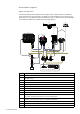
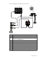
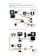
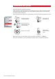
Connecting BR24 Radar
B
C
D
E
H
H
F
G
J
I
K
L
I
G
A
Power
Scanner cable
SimNet
Network
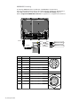
Brown RX-
White RX+
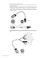
AT10HD
NMEA083 to SimNet
Converter Heading Only
Cut off 12 Pin
plug to expose bare wires
NMEA0183 10 Hz Heading
(e.g Gyro, Sat Compass)
Alternative: NMEA0183 heading
TX-
TX+
POWER
NETWORK
NETWORK NETWORK NETWORK NETWORK
+
_
Key Description
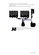
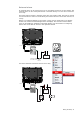
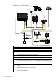
ANSO Marine Processor.
B BR24 BroadBand™ Radar scanner.
C Scanner cable. 20 m (65 ft) : Optional 10 m (33 ft) and 30 m (98 ft).
D RI10 Radar interface box.
E NEP (Network Expansion port) 5 port ethernet switch (or LLS-1 structure scan
module that has a built in 3 port Ethernet switch).
F Ethernet adapter RJ45 male to 5 pin yellow female
G Ethernet cable 5 pin yellow. BR24 comes with a 2 m (6.5 ft) 5 pin cable. See
Ethernet cables yellow on page 86 for more cable length options.
H SimNet Drop Cables: The BR24 and NSO are connected to the SimNet back-
bone. BR24 uses heading at 10 Hz to calculate MARPA and enable radar overlay.
I SimNet backbone. Refer to SimNet section on page 30.
J Power 12-24 V DC. Make sure yellow power on wire of BR24 is connected to
power.
K For MARPA and radar overlay a heading sensor is required. Use a SimNet /
NMEA2000 heading sensor such as the RC42.
L If a NMEA0183 10 Hz heading sensor is installed, convert to NMEA0183 to
SimNet using an AT10HD.