
Installation manual

10 | Overview
Overview
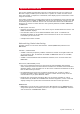
1
2
3 4
5
9 10
11
12
7
3
6 8
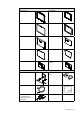
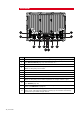
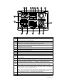
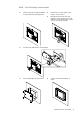
Key Description
1 Power. For power input 12 or 24 V DC input (see power page 25)
2
Utility. NMEA0183 Port TX (see NMEA0183 Wiring page 40), External Alarm
(see External Alarm page 41), Remote Power on
3 AUX. Not used.
4
VIDEO 1. DVI-D Video out. Display 1 video out to connect to a DI10, DI15,
MO19 or third party DVI monitor.
5 Power On/Off. Power control button.
6 Power LED. Indicated Power status.
7 HDD LED. Indicates hard drive activity.
8 LINK LED. Indicates if there is a valid Ethernet network connection
9
VIDEO 2. DVI-I Video out. Display 2 video out to connect to a DI10, DI15,
MO19 or third party DVI monitor. Duplicates the output of Video 1 port
10
SimNet. Connects the marine processor to a SimNet or NMEA2000 network
(see SimNet page 30).
11
Network. Ethernet network port for connecting to other Ethernet network de-
vices. (see Ethernet on page 37)
12
USB. Used to connect the supplied SD Card Reader for Software updates,
chart cards, chart data base updates, backing up of user data and settings.
Connection of portable storage devices.