Installation Manual Simrad NSO Multi-Function Display English www.simrad-yachting.
Blank page
Preface Disclaimer As Navico is continuously improving this product, we retain the right to make changes to the product at any time which may not be reflected in this version of the manual. Please contact your nearest distributor if you require any further assistance. It is the owner’s sole responsibility to install and use the instrument and transducers in a manner that will not cause accidents, personal injury or property damage.
Compliance Statements The Simrad NSO complies with the following regulations: • FCC Part 15 • CE compliant per EN60945 • C - Tick For more information please refer to our website: www.simrad-yachting.com. Warning The user is cautioned that any changes or modifications not expressly approved by the party responsible for compliance could void the user’s authority to operate the equipment.
Contents Preface ...................................................................................................1 Introduction ...........................................................................................7 About this manual .................................................................................. 7 Conventions .......................................................................................... 7 Important safety and warning information........................................
External alarm ..................................................................................... 41 Connecting BR24 Radar ....................................................................... 42 Connecting HD Radar ........................................................................... 43 Dual Radar Support .............................................................................. 44 BR24 and HD radar ............................................................................
Seastate filter ................................................................................... 65 Setting sailing parameters .................................................................. 65 Manually adjusting steering parameters................................................ 66 Echosounder setup ............................................................................... 69 Depth offset .....................................................................................
SimNet accessories .......................................................................... 86 Ethernet cables (yellow) ..................................................................... 86 Ethernet cables (RJ45 adapters) .......................................................... 87 Specifications .......................................................................................88 Supported NMEA0183 sentences ............................................................ 89 NMEA 2000 PGN List ......
Introduction About this manual This manual is a reference guide for installing the Simrad NSO Multi Function Display. The information in this manual at the time of printing is correct to the best of our knowledge. Navico can not be liable for any inaccuracies or missing information. Due to the constant improvement of Navico’s products. Navico cannot be liable for changes between the product and the manual. Refer to www.simrad-yachting.com for the latest manuals and addendums.
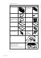
Check the parts NSO Processor Packaged parts list NSO Marine Processor OP40 Controller w/4 m (13 ft) Micro-C to SimNet cable Power cable 2m (6.
DI10 and DI15 display parts DI15 Display DI10 Display DI15 Bezel DI10 Bezel DI15 Dust cover DI10 Dust cover DI15 Gasket DI10 Gasket DI15 Cut-out Template DI10 Cut-out Template Common DI10 / DI15 display components Mounting bracket Mounting Bracket knobs Display power cable Cleaning cloth DI Display 5 x SCREW,14G x 1,PAN POZI,S/T,SS 316,BLACK Introduction | 9
Overview 1 12 2 11 3 4 5 7 6 3 Key 10 | Overview 9 10 8 Description 1 Power. For power input 12 or 24 V DC input (see power page 25) 2 Utility. NMEA0183 Port TX (see NMEA0183 Wiring page 40), External Alarm (see External Alarm page 41), Remote Power on 3 AUX. Not used. 4 VIDEO 1. DVI-D Video out. Display 1 video out to connect to a DI10, DI15, MO19 or third party DVI monitor. 5 Power On/Off. Power control button. 6 Power LED. Indicated Power status. 7 HDD LED.
2 3 1 DISPLAY MOB 16 GO TO VESSEL 6 MNO CHART RADAR 8 TUV 9 WXYZ ECHO NAV 0 PWR INFO PAGES 1 3 4 GHI 5 JKL 7 PQRS 15 DEF 14 7 8 9 OUT IN PLOT MARK 2 ABC STBY AUTO 4 5 6 13 10 MENU WIN 12 11 Key Description 1 MOB. Man Overboard. A long press will position a Man Over Board (MOB) waypoint at the vessel’s current position 2 Display Under Command LEDs. Indicates which display the OP40 is controlling.
Installing the NSO components Mounting location Choose the mounting locations carefully before you drill or cut. The display should be mounted so that the operator can easily use the controls and clearly see the display screen. Be sure to leave a direct path for all of the cables. Simrad displays are highcontrast and anti-reflective, and are viewable in direct sunlight, but for best results install the display out of direct sunlight.
DI10 / DI15 Display Panel mount 1 Attach the flush mounting template to the selected mounting position. 2 Drill the four corner radius holes using a 10 mm (3/8 ”). 3 Drill pilot holes for the four self tapping screws used to secure the display. If using M4 machine screws use a 5 mm (3/16”) drill bit. 4 Cut along the indicated on the template. 5 Secure the display to the surface.
DI10 / DI15 Display Bracket Mount An alternative to flush mounting the DI10 or DI15 is to bracket mount the display. The display may be tilted for best possible viewing angle when bracket mounted. 1 Use the lower half of the bracket as a template to mark the screw hole location. 2 Drill pilot holes and hole for cables if required 3 Secure the bracket base to the surface.
OP40 Panel Mount 1 Secure the flush mount template in the desired location 2 Drill the four holes to suit M4 machine screw or pilot hole for a self tapping #8 screw 3 Use a 38 mm (1.5") hole saw to cut corner radius 4 Cut along line indicated on the template and remove waste material 5 Secure the OP40 and gasket the surface.
Card Reader Installation The card reader connects to the USB port of the NSO MPU.
System architecture This section explains how the NSO connects to other devices as part of a system. The NSO has a highly scalable system architecture. A system can consist of a basic stand alone chart plotter, or expand to a networked, multi-display system connected to a wide range of accessories.
Data Bridging • Supported NMEA0183 sentences entering the system are bridged (converted) to SimNet / NMEA2000 and distributed on the SimNet backbone for all other displays to use • Certain SimNet /NMEA2000 PGNs (messages/sentences) are bridged across to NMEA0183 to be available as an output from any NSO / NSE processor • Ethernet to SimNet: Limited data is bridged from the Ethernet echosounder. Speed, depth and temperature are bridged to SimNet and NMEA0183.
Single station configuration possibilities Supplied with NSO system DISPLAY MOB 1 4 GHI 7PQRS Optional accessory POWER SD Card reader OP40 STBY AUTO 2 ABC 5 JKL 3 DEF IN DI15 OUT PLOT MARK GO TO VESSEL RADAR 6 MNO CHART 8 TUV 9 WXYZ ECHO NAV 0 PWR INFO PAGES MENU Repeat output to Simrad DI15, MO15, MO19or 3rd party DVI Monitor WIN VIDEO IN Connect 1 x Composite video to a MO19 or 3rd party Monitor 12 or 24 V DC HD RADAR Fuse Black NSO Fuse Red _ + VIDEO 2 Yellow/Gree
NMEA0183 Out DST800 RI10 RD68 RX - TX - BR24 TX + 20 | System architecture RX + SimNet to Micro-C cable 7 way joiner Card Reader T Or P OP40 GS15 GPS Ant Single NSO15 RC42 AIS NAIS-300 Suggested system VHF AC 12 P J1 J3 J2 RF25 J1 J3 J2 IS20 J1 T T-joiner J2 SimNet power 12 V DC (with terminator) J3 IS20 SimNet backbone SimNet drop cable Ethernet SimNet terminator IS20 Optional Sailing Instruments
BR24 DISTRESS 16/9 +/- 3 CH SCAN WX IC ESC CALL MENU SimNet power 12 V DC NMEA0183 Out RS25 P SQL PWR VOL RC25 T CH Ethernet DVI Video SimNet backbone SimNet drop cable SimNet terminator info RX - TX - H/L TX + 16/9 RX + System architecture | 21 RI10 P 12 V DC 5 Amp T AIS NAIS-300 GPS Ant OP40 RC42 VHF NSO & NSE Suggested system NSO DI15 NSE AC 12 WM-2 USA only RF25 i-Pod Dock LSS-1 Transducer: optional two transducer kit for high deadrise hulls LSS-1 Sonic Hub
P J3 J2 LSS-1 Optional Second Transducer HD Radar processor J1 AP28 J3 AT10-HD J1 LSS-1 Transducer BSM-1 NSO Marine Processor LSS-1 J2 IS20 Graphic DI15 * Station 1 3 DEF 6 MNO INFO ECHO CHART PLOT MARK IN OUT PAGES NAV RADAR GO TO VESSEL MENU BSM-1 Transducer Sonic Hub VHF RS82 BB 7 way joiner WIN 7 way joiner PWR 9 WXYZ 2 ABC 5 JKL 8 TUV 0 STBY AUTO 1 4 GHI DISPLAY 7PQRS MOB OP40 iPod Dock P T AC 42 AI50 AIS NETWORK NETWORK NETWORK RS82 H/S NEP-2 VHF
System architecture | 23 HD RADAR Processor AT10HD Video HD RADAR Processor AT10HD Large NSO and NSE NSO MO19 Monitor DI15 Display Suggested system HD Radar HD Radar LSS-1 Transducer Optional 2nd transducer for high deadrise hulls LSS-1 OP40 P 12 V DC 5 Amp Card Reader NEP-2 OP40 Station 1 OP40 Station 2 RS87 H/S BSM-2 NSO MO19 Monitor DI15 Display RS87 H/S VHF LSH80 Hailer AC 12 RC42 T AIS NAIS-300 RF25 NSE-8 or NSE-12 Station 3 SimNet Inline Joiner with terminator Sim
Wiring the NSO Wiring guidelines Most installation problems are caused by shortcuts taken with system cables. When wiring the NSO, follow the guidelines below.
Power NSO Marine Processor NSO Power Connector 1 2 3 Power Cable (000-00129-001) 2 m (6 ft) Pin Wire color Function 1 Black Battery (-) 2 Red Battery (+) 3 GRN / Yellow Ships Ground if available 12 - 24 V DC Connecting power • NSO marine processor ships with a 6 ft (2 m) power cable.
Remote Power On The NSO MPU can turned on by an external powered switch connected to the light green wire of the Utility cable. Voltage applied by the switch needs to be >5 V DC. Note: Removing voltage from the light green wire will not shut down the NSO.
MO19 Monitor Connections. Note: MO19 is 24 V DC Only RGB DVI Port _ + Optional Y Cable for RGB connection. Video 2 Port only 24 V DC Only DI10 and DI15 Video connection DI10 and DI15 Power connection DI10 and DI15 Power cable DI10, DI15 Power cable DI10, DI15 Display Power Connector 1 2 4 3 4 3 1 2 Pin 1 & 2 Black. Battery (-) Pin 3 & 4 Red.
Video Out The NSO Marine Processor has 2 DVI connectors. Video 1 is a DVI-D port supporting just a DVI digital display or monitor. DI10 DI15 MO19 or 3rd party DVI Monitor Both video ports output the same information at the same resolution, so if using DI10 or DI15 displays both screen sizes have to be the same size. However a monitor with a built in scaler such as MO19 can be combined with a different size display.
Video 2 is DVI-I, which can support a DVI display monitor and also with the use of an optional Y cable, can also output to an RGB monitor. DI15 MO19 or 3rd party RGB Monitor DI15 Y Cable Video-Out cable part number options Part Number Description AA010152 3 m (9.8 ft) Video cable DVI-HD26 for DI10/DI15 AA010154 10 m (33 ft) Video cable DVI-HD26 for DI10/DI15 AA010159 0.3 m (1 ft) Y Cable. DVI-DVI/RGB AA010162 5 m (16.
SimNet SimNet is a data network based on NMEA2000 CAN bus technology that makes interconnection and integration of Simrad and NMEA2000 products simple. SimNet permits the exchange of data between the interfaced products and enables the flow of commands and instructions between the various SimNet and NMEA2000 compatible products. The data transfer capability of SimNet is 50 times higher than the NMEA0183 standard at 4800 baud.
• Certain Simrad products have two SimNet connectors, which can be made to be part of the backbone.
The drawing below shows a small SimNet network. Power is introduced at one end using a SimNet power cable with termination ending with a second terminator. H I F G G T T + - 12 V DC A B C D SimNet drop cable E SimNet power T Key 32 | Wiring the NSO SimNet terminator Description A SimNet power source.
A slightly larger system below. Power is connected at one end using terminated power cable. A second terminator is required at the end of the backbone. I H SimNet SimNet SimNet SimNet T drop cable backbone power terminator G F Menu Menu K T T _ J + 12 V DC A BC D E Key Description A SimNet power source.
For larger systems introduce power at central point in the backbone to “balance” the voltage drop of the network. Use SimNet cable without termination (yellow cap) (24005910) G I T F F Menu Menu H E G H _ + 12 V DC A B C F D Menu T I H E SimNet drop cable SimNet backbone SimNet power cable T Key 34 | Wiring the NSO SimNet Terminator Description A SimNet power source.
Integrating SimNet and other CAN networks Increasingly there are vessels that will have NMEA2000 based networks provided by different manufacturers. If networks from different manufacturers are required to share data, it is important to plan how both networks are going to interface to each other.
When interfacing to C-ZONE or another NMEA2000 network it is recommended to use a BEP Network interface bridge (A) to join the two network backbones together. C-ZONE / NMEA2000 Network interface bridge isolates the power of the two networks but allows data to be freely shared between. The Network Interface has built in terminators so needs to be placed at the extremity of each network backbone.
Ethernet The NSO system uses an Ethernet network to interconnect high bandwidth devices such as radar and echo sounder. The NSO marine processor has one Ethernet network port with an RJ45 connector. A short RJ45 male to 5 pin female cable 160mm (6") is included with the NSO and is fitted to the NETWORK port.
Connecting NSO to one other Ethernet performance module Using the supplied RJ45 to 5 Pin yellow adapter, any one of the Ethernet performance modules using one of the 5 Pin Yellow Ethernet cables can connect directly to an NSO Ethernet performance modules BR24 BSM-1 BSM-2 LSS-1 WM-2 WM-2 NSO RJ45 to Yellow 5 Pin female Ethernet adapter (crossover) Yellow 5 Pin Ethernet cables Connecting directly to HD Radar NSO RJ45 to Yellow 5 Pin female Ethernet adapter RED (crossover) HD Radar RJ45 to Yellow 5 Pi
Connecting to two or more performance modules Connecting to more than one Ethernet device will require using a Ethernet network switch such as NEP-2.
NMEA0183 wiring To exchange NMEA0183 data, the NSO has one NMEA0183 communication. The port uses RS232 protocol and can be configured in the software for different baud rates. NMEA sentences can be turned on or off.
External alarm An external alarm can be connected to one or more NSO processors on the network. The external alarm can be a small peizo buzzer connected directly or a horn siren connected via a relay. The external alarm output is the dark green wire on the Utility cable. This pulls to ground to sound the alarm. If the current drawn by the external alarms is more than 250 mA, fit a relay. Alarms are configured globally in the system i.
Connecting BR24 Radar B SimNet Network Power Scanner cable A C E POWER NETWORK D F NETWORK NETWORK NETWORK NETWORK H H G G I I K J L _ + White RX+ Brown RX- AT10HD NMEA083 to SimNet Converter Heading Only TX+ TX- Cut off 12 Pin plug to expose bare wires NMEA0183 10 Hz Heading (e.g Gyro, Sat Compass) Alternative: NMEA0183 heading Key 42 | Wiring the NSO Description A NSO Marine Processor. B BR24 BroadBand™ Radar scanner. C Scanner cable.
Connecting HD Radar 2 kW 12 V DC ONLY 4 kW & 6 kW 12 or 24 V DC 10 kW & 25 kW 24 V DC ONLY Scanner B Optional 2nd HD Radar AT10HD Ethernet C A M D E POWER NETWORK H NETWORK F NETWORK NETWORK H NETWORK G G I I J L K K _ + White RX+ Brown RX- AT10HD NMEA083 to SimNet Converter Heading Only K TX+ TX- Cut off 12 Pin plug to expose bare wires NMEA0183 10 Hz Heading (e.
Dual Radar Support BR24 and HD radar Interference will be seen on BR24 at most ranges, when a pulse radar is transmitting at the same time on the same boat. It is Navico’s recommendation to only transmit one radar at a time: e.g. BR24 for typical navigational usage, or pulse radar to locate weather cells, defined coastlines at a distance and to trigger Racons.
Connecting BSM-1 Broadband Echosounder F A 2 1 3 7 6 4 5 B POWER NETWORK E NETWORK NETWORK NETWORK NETWORK D C C _ + Key Description A NSO display B BSM-1 Broadband Echosounder module C Ethernet cable yellow 5 pin see Ethernet cables yellow on page for more cable length options.
BSM-1 Transducer adapter cables For vessels with existing transducers there are two adapter cables available to assist with BSM-1 installation. For vessels that already have an transducer that was used with older Navico products that has 6 pin connector. Use 000-00022-001 6 pin to 7 pin transducer adapter cable. These transducers will require the 10 k temp version of the transducer selected for transducer type in Echo Installation. See the Echosounder Setup section on page 69 for further information.
NSO Auto Pilot Integration An NSO can be used as a control head for the Simrad AC12 or AC42 Auto pilot computers. It can be used as the sole control head unit or in parallel to AP24 or AP28 control head units.
Commission the system Operating the menu system In this manual you will see few direct text references to keys, menus and menu entries, and few step-by-step descriptions. By using graphics we will guide you to the key and the required menu selections.
Turning on for the first time From the factory the OP40 controller is not assigned to control any NSO processors and will not be responsive until it as been assigned to control an NSO or NSE processor.
Unassign a display from an OP40 9 MENU WIN Configure the next OP40 To take command of another OP40 in configuration mode press and hold the DISPLAY key for 1 second MOB DISPLAY 1 Sec Finish OP40 configuration To Exit out of OP40 configuration mode press X 9 MENU WIN OP40 LED sequences Steady Red: Processor assigned to LED position 1 powered OFF Steady Green: Processor assigned to LED position 1 powered ON Flashing Green: Power button has been pressed and the processor is starting up All LEDs s
Turning on / off: Normal operation Normal operation mode of turning the unit on /off after OP40s have been configured POWER ON 1MOB 2 ABC 3 DEF 4 GHI 5 JKL 6 MNO 7 PQRS 8 TUV STBY AUTO 0 STAND BY 1MOB 2 ABC 4 GHI 5 JKL 6 MNO 7 PQRS 8 TUV 9WXYZ STBY AUTO 0 POWER OFF 3 DEF 3s PWR 9WXYZ PWR PWR A quick press of the PWR button will start the system: note it may take a few seconds for something to appear on the screen.
System settings menu 9 To access the system settings menu press x2 MENU WIN Language Language used on menus and dialog boxes Step 1 PLOT MARK Step 2 PLOT MARK GOTO VESSEL Choose Language Step 3 PLOT MARK GOTO VESSEL Select Language Notes The display will need to be restarted for change to take effect GOTO VESSEL Yes to restart Time: Local Time, Time format, Date Format Step 1 PLOT MARK Step 2 Step 3 Local time (Time Offset) against GMT from the GPS.
Commissioning checklist The NSO has a number of advanced features which can be configured through the settings menu. It is recommend you become familiar with the operation of the unit using the default settings before making any changes to these menus. Settings menus will vary depending on the optional sensors and devices attached. Before changing system settings make sure that all displays are powered on as a lot of settings are global and are shared across the Ethernet network.
Set antenna height: HD and Broadband Radar Set zero bearing: HD and Broadband Radar (note, perform heading sensor calibration first Set zero range (main bang): HD Radar Adjust for local interference: Broadband Radar Park angle: Open array HD Radar Heading sensor calibration AIS Enter own ships MMSI number Back up settings Create a backup of the display settings and transfer to portable drive or SD card 54 | Commission the system
Data setup Data set up is required on initial start up of the system, or if any part of the SimNet or NMEA 2000 network has been changed or replaced.
There are ten categories of sources such as Compass, Navigation, Position etc. Under each of these categories a display can be set to receive data from sources as part of the Simrad group or receive the source data independently from the group (None) The example below shows the available options for position sources, and that the GS15 GPS is used by all displays with group selection set to Simrad. If you selected the GS10 all displays in the Simrad group would use the GS10 GPS.
SimNet Groups The SimNet Group function is used to control parameter settings, either globally or in groups of units. It groups parameter settings such as backlighting, units and alarms. The function is used on larger vessels where several units are connected via the SimNet network. By assigning several units to the same group, a parameter update on one unit will have the same effect on the rest of the group members. The following example shows a two station installation.
Damping Controls how quickly instruments respond to changes in values from sensors. Damping can be used for heading, wind, boat speed and depth instruments. Increasing the damping applies more averaging or smoothing of the data update rate on the instrument or display. Damping settings are applied to SimNet displays and Instruments belonging to particular damping SimNet Groups.
Speed Calibration (SimNet Transducers) Water speed off set Water speed calibration is used to adjust the speed value from the paddle wheel to match the actual speed. This can be measured either from the GPS speed over ground (SOG) or by timing the boat over a known distance. Water speed calibration should be performed with as little wind and current movement as possible. Select Auto correct to match water speed to ground speed Manual calculation. If in average the water speed reads 8.
Autopilot Setup If an AC12 or AC42 autopilot computer is connected to the NSO system, autopilot functionality will be included in the NSO. The NSO can be connected to a full autopilot system including an AP24 or AP28 control head, or the NSO can be used as the only control head in the autopilot system. Wiring the autopilot system The AC12/AC42 is connected to the NSO system using the SimNet network.
x2 MENU WIN When the autopilot computer is delivered from factory AND ANY TIME AFTER AN AUTOPILOT RESET HAS BEEN PERFORMED, you will have to run a complete setup again. All steps in all commissioning procedures are clearly described on-screen, and you will be guided step by step through the process.
- When this test is started the autopilot computer will issue a series of PORT and STBD rudder commands and automatically verify correct rudder direction. It detects minimum power to drive the rudder and reduces the rudder speed if it exceeds the maximum preferred speed (8°/sec.) for autopilot operation. The system will also detect whether the drive unit is a reversible motor or if a solenoid valve is operated.
- Compass calibration; used to automatically compensate for on-board magnetic interference - Compass offset adjustment, used to compensate for a fixed offset in the final heading readout - Wind calibration to compensate for a fixed mechanical offset of the Wind vane - Boat speed calibration - Transition HI/LO speed setting (the speed at which you want to change the set of steering parameters) - Automatic tuning of the steering parameters - Setting the seastate filer - Saiboat setup Compass c
LUBBER LINE 20% Magnitude of local field in % of earth’s magnetic field. 10 Direction of local field with respect to lubber line. It can also be on the reciprocal. In certain areas and at high latitudes the local magnetic interference becomes more significant and heading errors exceeding ±3° may have to be accepted. Compass mounting offset After compass calibration, the difference between the compass lubber line and the boat’s center line should be compensated for.
LO HI p res on se p res on se Transition to LO parameters with increasing speed: 10kn Transition speed set to 9kn Transition to HI parameters with decreasing speed: 8kn Active response parameter set is shown in the autopilot popup, and the following abbreviations are used: HI-A High response parameters set automatically LO-A Low response parameters set automatically HI-M High response parameters set manually LO-M Low response parameter set manually Autotuning The autotune feature will run t
Range Change per step Default Units 2 - 50 1 12 seconds Tack angle This value is used to preset the course change used when tacking in AUTO mode. By pressing the left/right arrow keys the course will change as much as this value. Range Change per step Default Units 50 - 150 1 100 ° Wind function With wind function set to Auto, the autopilot will automatically select between apparent and true wind steering. Auto is default and recommended for cruising.
Rudder This parameter determines the ratio between commanded rudder and the heading error. The higher rudder value the more rudder is applied. If the value is too small it will take a long time to compensate for a heading error, and the autopilot will fail to keep a steady course. If the value is set too high the overshoot will increase and the steering will be unstable. Counter rudder Counter rudder is the amount of rudder used to try to prevent the boat from yawing around the set course.
The settings are used for the tack-prevent function. They also applies when the autopilot is operating in WindNAV mode. Refer to the Operating the autopilot section. You can select different minimum wind angles for port and starboard. The difference between port and starboard will be taken into account when calculating the Distance To Turn (DTT).
Echosounder setup Depth offset This is a value that can be entered on the Echo Installation page to make the depth represent either depth below the transducer or depth below the surface. A) Depth below Keel value: Is the distance from transducer to the keel: Enter a negative value. B) Depth Below Transducer: no offset required. C) Depth Below Surface (waterline) value: Is the distance from transducer to the surface: Enter a positive value.
Transducer type (Echosounder) Transducer type is used for selecting the transducer model connected to the echo sounder module. In some transducers with built-in temperature sensors, the temperature may not be correct if the correct transducer is not selected from the transducer type menu.
Radar Transmit, Standby or off Press Radar function button to display the radar 9 MENU WIN Press Menu to bring g up radar options To make radar adjustments. • 9 select item to adjust PLOT MARK GOTO VESSEL MENU Adjust the setting value as needed Setting value is displayed on screen WIN To confirm Broadband Radar™ Interference from some onboard sources can interfere with the Broadband radar.
Serial port setup Configure the serial port to match the NMEA0183 device that it is connected to. Baud Rate (common for input and output) Step 1 Step 2 Step 3 PLOT MARK PLOT MARK GOTO VESSEL Select Baud Rate GOTO VESSEL Select OK NMEA 0183 output Select the desired NMEA0183 sentences to be transmitted. (see Supported NMEA0183 sentences page 89). Uncheck NMEA0183 output to turn off all sentences. Output rate is shown.
Fuel and Engines If the vessel has an NMEA2000 interface to its engines and fuel tanks the NSO can display the following fuel consumption information: • Fuel used since last fill • Fuel used on current trip • Fuel used during the season Calibration of the tanks is needed to display accurate fuel levels. Vessel Setup For engine information make sure to configure the system to how many tanks an engines are on the vessel AIS own vessel If an AIS system is installed.
Diagnostics NMEA2000 Diagnostics Bus State: Indicates if SimNet backbone is operating: Check power: Check termination RX Overflows / Overruns greater than 0 could indicate the software is very busy and unable to keep up with incoming messages. RX / TX Errors: CAN interface error counters. Count up when there are errors on the CAN bus, and down when things are Ok. Should normally be 0. Goes bus off when 255 is reached. Check same things as for Bus state if greater than 0 observed.
CZone Setup BEP CZone is a NMEA 2000 compliant (SimNet) system that can monitor AC and DC circuits, as well as control DC circuits. It also features onboard diagnostics, multifunction timer capabilities, dimming control and handles a wide DC voltage range (9-32V DC). When connected on the same NMEA 2000 network, the NSO provides a clear and intuitive user interface for the CZone system.
Check GPS signal Press direct access key PAGES >3 System backup A backup of all the NSO settings such as page layouts, custom instruments can be made at any time, and either stored on the NSO or transferred to a USB key or SD Card Press direct access key PAGES > 9. Name the backup using the alphanumeric key pad. Press MENU select copy. Select destination to copy file too. Restore a backup To restore or import a backup, Select the file, Press menu and select import.
Backup Waypoints routes and tracks 1 Press the PAGES direct access key along the bottom of the screen. 2 Select “Files” or press “9” on the alphanumeric keypad. 3 Select Waypoints Routes and 4 Select the desired file format, then Tracks, then press press 9 9 MENU MENU WIN WIN 5 Select the Portable Drive as the Destination folder...
Software upgrades Download the latest software from www.simrad-yachting.com Software upgrades can be performed on the following types of devices from any NSO or NSE display. • NSO / NSE Marine processors • SimNet devices • Ethernet devices The same procedure is used to upgrade software on all types of devices. Upgrade files for different types of devices have different file extensions. NSO /NSE displays xxx.xxx.xxx.UPD Ethernet devices device.RIW SimNet / NMEA2000 devices Device_x.x.xx.xx.swup (or .
Ethernet module software version Example below shows upgrading a SimNet IS20 Combi instrument but is the same for NSO displays 2 Press function button PAGES 1 Copy upgrade files on to a USB Stick or SD card 3 Select Memory card 4 Press Menu 9 Press 9 or navigate to files button MENU WIN Select Upgrade Select the upgrade file Insert USB Stick or SD card into USB port or card reader NSO or NSE Processor upgrade Important things to remember EACH NSO MUST BE UPGRADED INDIVIDUALLY (THERE IS NO NETW
5 Highlight OK to confirm that you want 6 to upgrade your display then press The NSO will automatically shut down and restart. After 10 seconds there will be a Simrad logo and after another 20 seconds basic text will prompt you to upgrade or start normally.Press the “1” key followed by the key to start the upgrade or the “0” key to cancel and start normally The following updates were found: 7 The Upgrade will start. At this stage do not remove the Portable Drive turn off the NSE.
Screen capture It is possible to capture a snap shot of the current screen 1 Enable screen capture 3 Short press on PWR button to capture screen shot 1MOB 2 ABC 3 DEF 4 GHI 5 JKL 6 MNO 7 PQRS 8 TUV 9WXYZ STBY AUTO 0 2 Create desired screen to capture 3 Browse to the desired screen shot to copy 4 Press MENU and select Copy 5 Select the USB Drive or SD card as the location to copy the file too.
NSO Drawings 262 mm (10.32") NSO Dimensions 352 mm (13.86") 73 mm (2.87") 143 mm (5.63") MO19 Dimensions 425 mm (16.73") 83 mm (3.27") 260 mm (10.23") 3 mm (0.11") 91 mm (3.58") 200 mm (7.87") R 6 mm 381 mm (15.00") " 19 387 mm (15.24") 431 mm (16.
DI15 Dimensions 63.50 mm (2.5”) 325.73 (12.82”) 290 mm (11.42”) 373.90 mm (14.72”) 15 “ 9 mm 70 mm (2.
OP40 Dimensions 25.0 mm (1.00") 101.4 mm (3.94") 108.0 mm (4.25") 158.7 mm (6.25") 18.0 mm (0.70") 65 mm (2.56") 112.5 mm (4.43") 164.5 mm (6.48") NSO Chart Card Reader Dimensions 69 mm (2.71") 35 mm (1.47") 57 mm (2.24") 14 mm (0.55") 45 mm (1.77") 41 mm (1.
Spare parts NSO Spare parts Part Number Description 000-10290-001 NSO Marine Processor AMER 000-10292-001 NSO Marine Processor EMEA 000-10291-001 NSO Marine Processor ROW 000-10298-001 OP40 Controller 000-10349-001 OP40 Cover 000-0139-001 OP40 Rotary knob 000-10299-001 NSO Chart card reader 5 m (16.
SimNet accessories Part Number SIMKIT-1 Description SimNet Starter Kit: Includes • 24005845 SimNet 5 m (16.5 ft) cable • 24006298 SimNet 7-Prong Multi-Joiner • 24005894 SimNet Termination Plug • 24005902 SimNet 2 m (6 ft) power cable w/terminator SIMKIT-2 SimNet Starter Kit with one AT10 NMEA0183 interface • 24005936 AT10 two way general NMEA0183 to SimNet Converter • 24005837 SimNet 2 m (6 ft) cable • 24005845 SimNet 5 m (16.
Ethernet cables (RJ45 adapters) Part Number Description 000-10437-001 RJ45 to 5 pin yellow female (crossover) for NSO 000-10438-001 RJ45 to 5 pin yellow female (straight though) for HD Radar Spare parts | 87
Specifications Mechanical Back Case Die cast aluminium Heat Sinking Direct heat transfer from processor to casting Environmental Operating tempera- -15° C to +55° C (+5° F to +131° F) ture Waterproof integrity IPx5 Certificates of CE(EN60945:2002)/CTick Conformity Electrical Operating Voltage 12 or 24 V DC (9 - 34 V DC max) Processor Intel Pentium M 1.6 GHz RAM 512 MB Hard drive 80 GB User interface User interface Interface via OP40 controller.
Comms NMEA0183 1 x Transmit, 1 x Receive port External Alarm <250 mA Supported baud rates 4,800, 9,600, 19,200, 38,400 baud. Note: Port will transmit and receive at the set baud rate Ethernet 10/100 base Ethernet, one port Max number of displays/processors 4 in any combination NSO or NSE External Connectors Power, Utility (ext. alarm, NMEA 0183), SimNet (NMEA2000), (rear) Network (1 x ethernet, USB x 1, Video Out (1 x DVI-D, 1 x DVI-I), Aux.
NMEA 2000 PGN List NMEA 2000 PGN Receive 129284 Navigation Data 59392 ISO Acknowledgement 129539 GNSS DOPs 59904 ISO Request 129540 GNSS Sats in View 60928 ISO Address Claim 129794 61184 Parameter Request/Command AIS Class A Static and Voyage Related Data 65285 Temperature with Instance 129801 65289 Trim Tab Insect Configuration AIS Addressed Safety Related Message 65291 Backlight Control 129802 AIS Safety Related Broadcast Message 65292 Clear Fluid Level Warnings 129808 DSC Ca
NMEA2000 PGN Transmit 61184 Parameter Request/Command 65287 Configure Temperature INSOcts 65289 Trim Tab Insect Calibration 65290 Paddle Wheel Speed Configuration 65291 Backlight Control 65292 Clear Fluid Level Warnings 65293 LGC-2000 Configuration 126208 ISO Command Group Function 126992 System Time 126996 Product Info 127237 Heading/Track Control 127250 Vessel Heading 127258 Magnetic Variation 128259 Speed, Water referenced 128267 Water Depth 128275 DistanceLog 129025 Posi
NSE8, NSE12Installation Manual English, Doc.no.