
Installation manual


SimradES70
ThenewzoomfunctionprovidedbytheSimradES70isinnovative,efcientand
veryeasytouse.Usingthetrackballyoucanestablishanareaontheechogram.The
informationwithinthisareaisdisplayedintheZoompane,andtheshbiomassis
calculatedanddisplayed.Thezoomedareacanbeusedtoinvestigateaschoolofpelagic
sh,oranareaclosetobottom.
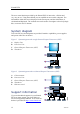
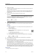
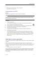
Systemdiagram
TwobasicES70systemdiagramsareprovided.Interfacecapabilities,powersupplies
andpowercablesarenotshown.
Figure1SystemdiagramwithasingleGeneralPurposeTransceiver(GPT)
A
B
C
D
PWR
MENU
Transducer
+5V
+12V
-12V
HV1
HV2
TX
RX
Fuse10A
115-230VAC
Fuse2A
S1
S2
12VDC
Auxiliary
Ethernet
GeneralPurpose Transceiver
DSP-6X IO
POWER
Ethernet
ADisplayUnit
BProcessorUnit
CGeneralPurposeTransceiver(GPT)
DTransducer
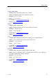
Figure2SystemdiagramwithtwoGeneralPurposeTransceivers(GPT)
A
B
C
D
PWR
MENU
Transducer
+5V
+12V
-12V
HV1
HV2
TX
RX
Fuse10A
115-230VAC
Fuse2A
S1
S2
12VDC
Auxiliary
Ethernet
GeneralPurpose Transceiver
DSP-6X IO
POWER
Ethernet
Transducer
+5V
+12V
-12V
HV1
HV2
TX
RX
Fuse10A
115-230VAC
Fuse2A
S1
S2
12VDC
Auxiliary
Ethernet
GeneralPurpose Transceiver
DSP-6X IO
POWER
Ethernet
E
(CD024216-002)
AColourmonitor
BProcessorUnit
CGeneralPurposeTransceiver(GPT)
DTransducer
EEthernetswitch
Supportinformation
IfyouneedtechnicalsupportforyourSimrad
ES70youmustcontactyourlocaldealer,or
oneofoursupportdepartments.Alistofallour
dealersisprovidedonhttp://www.simrad.com
.
12
343539/C