
Instruction manual


Robertson AP11 Autopilot
66 20220513E
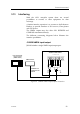
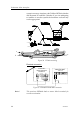
CDI35 Interface
Locate the CDI35 as close to the compass as possible so that
there will be no problem finding it in the event of a service.
Put the two fixing screws in the slots and secure the unit to
the bulkhead. Open the unit to access the screw terminals.
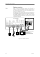
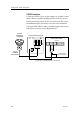
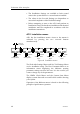
Cut the CD100 cable to make a suitable length and connect
both cables as shown on the diagram below.
* NON-POLARIZED
(COLOR INDEPENDENT)
JUNCTION UNIT
MAIN PCB
HS+
*
Heading
Sensor
HS
CDI35 INTERFACE PCB
BOAT'S
MAGNETIC
COMPASS
CD100
COURSE
DETECTOR
White
Brown
Green
Yellow
Grey
12
3
4
5
Figure 39 CD100/CDI35 connection