
Instruction manual


Robertson AP11 Autopilot
54 20220513E
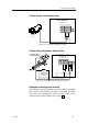
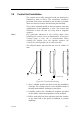
4. Open hole out using a 50 mm (2") cutter in a hand held
brace or electric drill. Drill the 4 fixing holes using a 2.5
mm (3/32") drill.
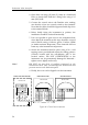
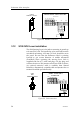
5. Connect the control unit to the Dataline wire, making
sure that the colors are correctly wired to the terminals.
Note that the cables should be supported with clips close
to the terminal blocks.
6. Before finally fixing the instrument in position, the
installation should be checked functionally.
7. If it is not possible to gain access to the instrument back
when fitted, the terminals at this stage should be covered
with a liberal coating of silicone grease, Vaseline, WD40
(or similar moisture dispersant). These materials will not
harm any other instrument components.
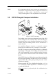
8. Secure the instrument head in place using 4 No. 6 self
tapping screws provided and ensure the sealing gasket is
correctly located with the self-adhesive side to the
location surface. DO NOT OVERTIGHTEN as the
instrument can be permanently damaged if distorted -
tighten screws lightly and evenly.
Note ! DO NOT use any form of sealing compound on the
instrument back. This can damage the instrument and
prevent access to the desiccant pack.
9. Finally, the cover can be clipped over the instrument.
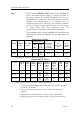
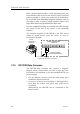
MAIN CONTROL UNIT
SECOND STATION
MAIN PCB
Bus
Bus +
Vsys+
Vsys
On-Off
Alarm
Bn Gry
Yel
Gn
WHITE
GREEN
BROWN
PINK
GREY
YELLOW
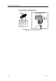
REAR SIDE
REAR SIDE
WHITE
GREEN
BROWN
PINK
GREY
YELLOW
WHITE
GREEN
BROWN
PINK
GREY
YELLOW
ROBNET
PnkWh
SCREEN
J3000X/J300X JUNCTION UNIT
Figure 24 Control unit connection