
Instruction manual


Robertson AP11 Autopilot
50 20220513E
Note ! When selecting DRIVE UNIT voltage in the Installation
setup, the clutch/bypass voltage is always set equal to
the motor voltage. If a retrofit installation where e.g. a
HLD2000 has a 12V motor and a 24V bypass valve, the
bypass valve solenoid has to be changed back to
standard 12V version. The drive unit output, terminals
A-B, is a "bipolar" output which means you do not have
to think about port and starboard. Also the
clutch/by-pass connection is independent of polarity.
The maximum drive current capabilities of the J3000X and
J300X junction units are different. Use the table below as
reference.
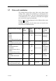
HYDRAULIC PUMPS
RAM CAPACITY
MODEL MOTOR
VOLTS
JUNCTION
UNIT
MIN
cm
3
(cu. in.)
MAX
cm
3
(cu. in.)
FLOW RATE
AT 10 bar
cm
3
/min
(cu. in/min)
MAX
PRESSURE
bar
PWR.
CONSUM-
PTION
RPU80 12V J3000X 80 (4,9) 250
(15,2)
800 (49) 50 2,5-6 A
RPU160 12V J300X 160 (9,8) 550
(33,5)
1600 (98) 60 3-10 A
Steering gear interface: Hydraulic plumbing
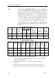
LINEAR DRIVE UNITS
MODEL MOTOR
VOLTS
JUNC-
TION
UNIT
MAX
STROKE
mm (in.)
PEAK
THRUST
kg (lb.)
MAX
RUDDER
TORQUE
Nm
(lb.in.)
HARD-
OVER
TIME
sec.
(30% load)
PWR.
CON-
SUMP.
TILLER
ARM
mm
(in.)
MLD200 12V J3000X 300 (11,8) 200
(440)
490
(4350)
15 1,5-6 A 263
(10,4)
HLD350 12V J3000X 200 (7,9) 350
(770)
610
(5400)
12 2,5-8 A 175
(6,9)
HLD2000L 12V J300X 340 (13,4) 500
(1100)
1460
(12850)
19 3-10 A 298
(11,7)
Steering gear interface: Connects to quadrant or tiller.
1. The motor voltage is stepped down by the junction unit when operating
from 24V or 32V mains.
2. The specified junction unit is necessary to achieve max drive unit
capacity.
3. Recommended operational thrust or torque is 70% of listed value.
4. Typical average power consumption is 40% of listed maximum value.