
Instruction manual


Instruction manual
20220513E 49
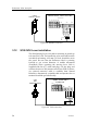
3.7 Drive unit installation
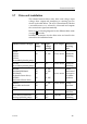
The relation between drive units, drive unit voltage, input
voltage, drive output and interfacing to steering gear are
shown in the table below. The AP11 system detects whether
a reversible motor or a solenoid is connected and outputs
the correct drive signal automatically.
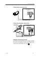
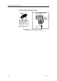
Refer to the connecting diagram for the different drive units
on page 51 onwards.
Installation instruction for the drive units are found in the
manual for the individual units.
Robertson Drive Unit type Drive unit
voltage
Input
voltage
(Mains)
Drive output Interface to
steer-ing
gear
RPU80,
RPU100
RPU150
RPU160
(Reversible hydraulic pump)
12V 12, 24V Revers. motor Hydraulic
plumbing
RPU200,
(Reversible hydraulic pump)
24V 24V Revers. motor Hydraulic
plumbing
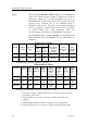
HLD350,
HLD2000/HLD2000L
HLD2000D
(Hydraulic linear drives)
MLD200
(Mechanical linear drive)
12V
12V
24V
12V
12, 24V
12, 24V
24V
12, 24V
Revers. motor
Direct
mechanical
connection
to rudder
quadrant
MRD100
(Reversible mechanical
drive)
12V
24V
12, 24V
24V
Revers. motor Chain/
sprockets
MRD150 12V 12, 24V Revers. motor Chain/
sprockets
RPU1/RPU3 (Continuous
running hydraulic pump)
12V
24V
12V
24V
Solenoids Hydraulic
plumbing