
Instruction manual


Instruction manual
20220513E 47
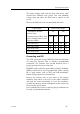
The mains supply cable and the drive unit motor cable
should have sufficient wire gauge. This will minimize
voltage drop and allow the drive unit to operate at full
power.
Refer to the table below for recommended cable sizes.
Cable length Drive Unit Voltage
1. Distribution Board to
Junction Unit.
12V 24V
2. Junction Unit to Drive Unit
motor. (Length refers to each
of the two cables)
AWG mm
2
AWG mm
2
Up to 3 m (10 ft.) 12 2,5 12 2,5
Up to 6 m ( (20 ft.) 10 4 12 2,5
Up to 10 m (32 ft.) 8 6 10 4
Up to 16 m (52 ft.) 6 10 8 6
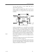
Grounding and RFI
The AP11 system has very good RFI protection and all units
are using the Junction Unit as common ground/shield
connection. The Junction Unit should therefore have a
proper ground connection to the hull.
ROBNET cables and other signal cables (compass, feedback,
NMEA) should not be run in parallel with cables carrying
RF or high current, such as VHF and SSB transmitters,
battery chargers/generators and winches.
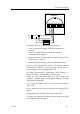
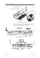
Remove the bottom cover to get access to the plug-in
terminals. Strip about 1 cm (0.4") of the cable's insulation
and pull the screen backwards to cover the insulation.
Position the straps as shown and tighten well to make sure
the screen has good contact.
Leave sufficient free wires so that the plug-in terminals can
be easily connected/disconnected.