
Instruction manual


Robertson AP11 Autopilot
46 20220513E
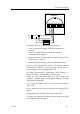
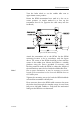
JUNCTION UNIT
MAIN PCB
Rudder
Feedb.
*
* NON POLARIZED
(COLOUR INDEPENDENT)
R
F
+
R
F
Figure 17 RF300 connection
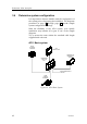
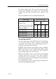
3.6 Junction unit installation
The J300X and J3000X junction units are not weatherproof
and should be mounted in a dry place between the control
unit and the drive unit. The junction unit is designed to
operate in a location that provides ambient temperatures
below +55°C (+130°F).
Figure 18 Junction unit - Bulkhead mounting
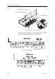
Cable connections
Use only shielded cables. This includes Mains input, drive
units and if necessary for the extension of the RF300 Rudder
Feedback cable. The clutch/bypass cable and the solenoid
cable should be 1,5 mm
2
(AWG14). Signal cables should be
0.5 mm
2
(AWG20) twisted pairs.