
Instruction manual


Robertson AP11 Autopilot
44 20220513E
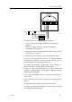
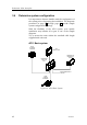
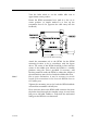
AP11 system with special J300X options
Figure 15 AP11 system with special J300X options
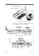
3.5 RF300 Rudder feedback installation
The RF300 Rudder feedback unit mounts close to the
rudders, and is mechanically linked to the rudder tiller arm
or rudder quadrant.
Refer to figure below for the recommended mounting
arrangement. Note that the RF300 transmitter arm has two
slots for the transmission link. The slots enable maximum
flexibility to provide the 1:1 mechanical linkage relationship.
Note ! Do not try to remove the transmitter arm from the
feedback unit. The unit is factory adjusted and need no
further adjustment at installation than described below.
As a starting point, it is desirable to set the transmitter rod to
the inner limit of the outer slot if possible. (Refer to figure).
Drill and tap the rudder tiller arm so that the Y1 dimension
is equal to the Y2 dimension (Use 4.2 mm drill and 5 mm
tap). Attach the ball joint to the tiller arm, and connect the
transmitter rod to the ball joint at the rudder tiller arm.
RFC35
FLUXGATE
COMPASS
RPU160
REVERSIBLE
PUMP
HLD2000L
HYDRAULIC LINEAR
DRIVE
RF300
RUDDER
FEEDBACK
J300X
JUNCTION
UNIT
DATABOX
IS11
INSTRUMENTS
CHART
PLOTTER
CLOCK DATA OUTPUT
FOR RADAR
IS11
SENSORS
WIND
DEPTH
SPEED
AP11
CONTROL UNIT
EXTERNAL ALARM
PLOTTER
NAV. RECEIVER
IS11 RUDDER
INSTRUMENT
IS11 COMPASS
INSTRUMENT