
Instruction manual


Robertson AP11 Autopilot
42 20220513E
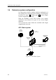
3.4 Determine system configuration
It is important to become familiar with the configuration of
the system prior to beginning the installation. The diagrams
presented on page 42 through page 44 provide sample
system configuration drawings.
With the flexibility of the AP11 system, your specific
installation may include all or part of one of the sample
diagrams.
Try to mount the units within the standard cable length
supplied with each unit.
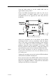
AP11 Basic system
RF C35
FLUXGATE
COMPASS
RPU 80/ RPU 160
REVERSI BL E
PUM PS
RF300
RUDDER
FEEDBACK
J3000X/J300X
JUNCTION
UNI T
AP11
CONTROL UNI T
MA I N S POWER SU PPL Y
12/24 VDC
Figure 12 AP11 Basic System