M A N U A L Simrad AP11 Autopilot A L W A Y S A T T H E F O R E F R O N T O F T E C H N O L O G Y
This page is intentionally left blank
Instruction manual Instruction Manual This manual is intended as a reference guide for operating and correctly installing the AP11 autopilot. Great care has been paid to simplify operation and set-up of the Robertson AP11, however, an autopilot is a complex electronic system. It is affected by sea conditions, speed of the vessel, hull shape and size.
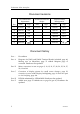
Robertson AP11 Autopilot Document revisions Documentation department Hardware/Software design Project/Product Management Rev Date Sign Date Sign Date Sign – 07.03.97 N.G. 07.03.97 G.K. 07.03.97 Th.H. A 10.07.97 N.G. 10.07.97 Th.H. B 16.02.98 N.G. 16.02.98 Th.H. C 28.09.98 N.G. 28.09.98 Th.H. D 26.01.00 N.G. 26.01.00 Th.H. E 02.01.02 02.01.02 Document history Rev. – First edition Rev. A Diagrams for J300X and J3000X Terminal Boards included, page 48.
Instruction manual Contents 1 2 INTRODUCTION...................................................................................................7 1.1 General ..........................................................................................................7 1.2 System Components....................................................................................8 1.3 AP11 Control Unit........................................................................................9 1.
Robertson AP11 Autopilot 2.15 Tacking in Auto Compass mode..............................................................27 2.16 Clutch/bypass switch.................................................................................27 2.17 Navigating with the AP11.........................................................................28 2.18 Auto Navigation Mode..............................................................................29 Nav. displays in Auto Navigation mode .......................
Instruction manual 4 3.9 RFC35 Fluxgate Compass installation .....................................................55 3.10 RFC35R Rate Compass ..............................................................................56 3.11 R3000X Remote Control installation........................................................57 3.12 S100 NFU Lever installation .....................................................................58 3.13 Interfacing ..........................................................
Robertson AP11 Autopilot 5 6 7 4.2 Junction Unit...............................................................................................86 4.3 Rudder Feedback .......................................................................................86 4.4 Compass ......................................................................................................86 4.5 Drive unit ....................................................................................................86 4.
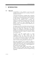
Instruction manual 1 INTRODUCTION 1.1 General Congratulations on the purchase of your new AP11 autopilot system and thank you for selecting a Robertson autopilot for your boat. Today Simrad manufacture a complete range of autopilots for all types of vessels, from leisure boats up to advanced steering systems for merchant marine vessels. Our factory for these products – branded Robertson – is located in Egersund on the south/west coast of Norway.
Robertson AP11 Autopilot The AP11 autopilot system includes NMEA0183 input and output ports. The NMEA input allows a single navigation receiver and speed and wind sensors to provide input to the system. The NMEA output provides heading and rudder angle to separate IS11 instruments or to the IS11 Databox. Depending on the autopilot configuration and the equipment that may be connected to the NMEA input, other NMEA data may also be available at the NMEA output.
Instruction manual RFC35 FLUXGATE COMPASS AP11 CONTROL UNIT RPU80/RPU160 REVERSIBLE PUMPS J3000X/J300X JUNCTION UNIT MAINS POWER SUPPLY 12/24 VDC RF300 RUDDER FEEDBACK Figure 1 AP11 Basic system 1.3 AP11 Control Unit 110 mm [4,33"] 50 mm Dia. [1,97"] ROBERTSON AP11 STBY-AUTO PWR RESPONSE DODGE MODE TURN AUTOPILOT 110 mm [4,33"] 17 mm 18 mm [0,67"] [0,71"] Figure 2 Control Unit Dimensions A compact autopilot control for panel or bulkhead mounting.
Robertson AP11 Autopilot 1.4 J3000X and J300X Junction Unit Figure 3 J3000X and J300X dimensions The junction unit is the heart in the AP11 autopilot system. It contains the steering computer, interface circuits to all system components and drive circuits for the drive unit motor and clutch. Two models, J300X and J3000X are available.
Instruction manual 1.5 RF300 Rudder Feedback Unit Figure 4 RF300 Dimensions Rudder feedback unit with transmission link and 10 m (30 feet) of cable. Transforms the angular travel of the rudder to a digital signal read by the autopilot steering computer. (See also optional linear feedback on page 13). 1.6 RFC35 Fluxgate compass Figure 5 RFC35 Dimensions A compact heading sensor from Robertson with 15 m (45 feet) of cable.
Robertson AP11 Autopilot 1.7 Optional components CDI35 Course Detector Interface Figure 6 CDI35 dimensions Interface unit to connect autopilot to magnetic compass with CD100 Course Detector. Provides excitation current for CD100 and converts the analogue sin/cos signal to digital format for the autopilot steering computer. RFC35R Rate compass Fluxgate compass with integrated rate sensor. Provides a dramatic improvement to the dynamic performance of both the autopilot and a stabilized radar display.
Instruction manual LF3000 Linear Feedback Figure 7 LF3000 dimensions Linear feedback unit for boats with outboard engine. Transforms the linear movement to an analogue signal. Supplied with 8,5 m cable and mounting clamps. LFI3000 Mk2 Linear Feedback Interface Figure 8 LFI3000 Mk2 dimensions Interface unit for LF3000 Linear Feedback. Converts the analogue LF3000 signal to the standard digital feedback signal for the autopilot steering computer.
Robertson AP11 Autopilot "Rudder" Indicator 110mm 50mm Dia. 110mm 17mm 18mm Figure 9 Robertson IS11 analogue display dimensions A 12 V Dataline instrument that can be connected directly to the NMEA output on the junction unit. Analogue display of boats' rudder angle. "Compass" Indicator A 12 V Dataline instrument that displays the boats heading on both digital and analogue format. Can be connected directly to NMEA output on the junction unit. Dimensions as for "Rudder" Indicator.
Instruction manual R3000X Remote Control A small hand-held remote control with two push buttons for power steering or course selection (port and starboard) and one push button with built-in lighted indicator for mode selection. S100 NFU steering lever 120 (4,75") Designed for in-door console mount. The lever has spring loaded return to mid- position.
Robertson AP11 Autopilot 2 AP11 AUTOPILOT OPERATION WARNING ! An autopilot is a very useful navigational aid, but DOES NOT under any circumstance replace a human navigator.
Instruction manual automatically if speed data is available, or can be set manually by the user. Three different backlighting colours are available for the LCD display and user settings are provided for lighting intensity and manual adjustment of steering parameters to "fine tune" the steering of a particular boat. Alarms are presented in plain English text to alert you of system and external data failure conditions.
Robertson AP11 Autopilot 2.2 On/Off A single push on the STBY-AUTO/PWR button switches the AP11 Autopilot ON. The display will show STBY-COM and display the boats heading. A long press (3-5 seconds) on the STBY-AUTO/PWR button switches the system OFF. As an additional safety, it is recommended that you locate the power breaker or mains switch before using the system for the first time. 2.
Instruction manual 2.4 Standby- Compass mode The (STBY-COM) mode is always entered when the AP11 is turned on. It is also the mode that is used when steering the boat manually. Rudder The rudder angle is shown on the bargraph and the compass heading is displayed and continually updated as the boat turns. ROBERTSON AP11 STBY-AUTO PWR RESPONSE DODGE MODE TURN AUTOPILOT 2.
Robertson AP11 Autopilot Press the STBY-AUTO button two times with an interval of approx. 2 seconds. The zero point is now set and the display will show: “Rudder” angle is 0° Rudder ROBERTSON AP11 STBY-AUTO PWR RESPONSE DODGE MODE TURN AUTOPILOT Operation Follow the operating instructions on the following pages. There is no further need for zero point settings until next time you turn the autopilot on. 2.
Instruction manual 2.7 NFU Steering Lever The rudder will move as long as the lever is offset to Port or Starboard. 2.8 Hand held remote REMOTE Push buttons for Port and Stbd NFU commands STBY-AUTO STBY/AUTO mode button. AUTO mode is when lamp is lit R3000X Note ! 2.9 When in AUTO mode, pressing the buttons will change the set course 1° each press. If you keep the button pressed, it will automatically change the course at a rate of 3°/second. Refer to page 35 for further information.
Robertson AP11 Autopilot Rudder Rudder or ROBERTSON AP11 STBY-AUTO PWR RESPONSE DODGE ROBERTSON AP11 STBY-AUTO PWR MODE TURN RESPONSE AUTOPILOT DODGE MODE TURN AUTOPILOT Bearing waypoint - waypoint Cross Track Error (XTE) The bearing waypoint to waypoint is only displayed if the Nav. source is transmitting valid data. If bearing is not available, the XTE display will show the magnitude of the cross track error and direction to steer back to track. 2.
Instruction manual 2.12 Auto Compass mode If needed, press the MODE button to select STBY-COM and put the boat on a straight course prior to entering the Auto Compass mode.
Robertson AP11 Autopilot When arriving within 10° of the new set course the display will change from TURN to AUTO-COM. You may then proceed with small (1°) course changes to set the final course. To re-take manual control, make a short press on the Stby-Auto button to select STBY-COM. Nav.
Instruction manual 2.13 Dodging The AP11 provides the capability for dodging. The Dodge function allows the user to temporarily take manual control of the boat's steering, when steering automatically on a set course. Dodging is very useful in situations where you need to quickly take control of the helm to steer around an obstruction, and then wish to return on the previous set heading after performing the evasive maneuver. Note ! Dodge is available in all Auto modes.
Robertson AP11 Autopilot 2.14 U-Turn The AP11 also provides a special U-turn feature that is available when the AP11 is in the AUTO mode. (If boat type set to "SAIL" in the installation set-up, a Tack function replaces the U-turn). U-Turn changes the current set course to be 180 degrees in the opposite direction. The user may decide if the U-turn should be made to Port or Starboard to bring the boat on the new course.
Instruction manual 2.15 Tacking in Auto Compass mode When the AP11 is installed on a sailboat, a fixed tack of 100 degrees can be made in AUTO mode. The use of this function should be carefully considered based on the boats characteristics and the weather situation. The tack function should only be used into the wind and must be tried out in good weather conditions with light wind to find out how it works on your boat.
Robertson AP11 Autopilot 2.17 Navigating with the AP11 The AP11 has the capability to use steering information from an external navigator (GPS, LORAN, Decca) to direct the boat to a specific waypoint location, or through a route of waypoints. In the AUTO NAV mode, the AP11 uses the heading sensor as it's reference for course keeping. The steering information received from the external navigator alters the set course to direct the AP11 to the destination waypoint.
Instruction manual received, the AP11 will continue on the current set course in Auto Compass mode. Note ! 2.18 Steering through a route of waypoints with the AP11 allows you the total flexibility for automatic waypoint sequencing, but combines the safety feature of requiring operator acknowledge for course changes in excess of 10 degrees. Auto Navigation Mode Enter STBY mode and use the MODE button to select STBY NAV.
Robertson AP11 Autopilot At the arrival of each waypoint: Arrows show direction that boat will turn to reach next WP. Press MODE to acknowledge course change Rudder Rudder ROBERTSON AP11 STBY-AUTO PWR RESPONSE DODG E ROBERTSON AP11 STBY-AU TO PWR MODE TURN RESPONSE AUTOPILOT DODG E TUR N AUTOPILOT XTE Display Boat is 0,1 Nm to the left of track after automatic course change.
Instruction manual 2.19 Wind vane steering In order to perform automatic wind vane steering the AP11 system must be operating in AUTO W/A mode, with valid input from wind sensor. The W/A function is an alternative to the NAV function and it is only available if the system has been set up for SAIL-boat in the Installation Setup Menu. W/A function can only operate when reaching as it is necessary to have a stable apparent wind.
Robertson AP11 Autopilot Changing set wind angle while in AUTO W/A mode: Rudder Rudder ROBERTSON AP11 STBY-AUTO PWR RESPONSE DODGE MODE TURN AUTOPILOT Short press on or to adjust set apparent wind angle. (1° each press) ROBERTSON AP11 STBY-AUTO PWR RESPONSE DODGE MODE TURN AUTOPILOT Alternatively: Press and hold < or > to adjust (jumps to 5° increments).
Instruction manual 2.21 Tacking in AUTO W/A mode The AUTO W/A mode on sail boats has also a tacking aid function. When activated it will take the boat from the course you are steering to a computed course that gives you the same apparent wind on the other side. This tacking function as compared to tacking in Auto Compass mode can only be used when you are sailing with the apparent wind as the reference, and with apparent wind angle less than 80-90 degrees.
Robertson AP11 Autopilot Nav. displays in Auto W/A mode ROBERTSON AP11 ROBERTSON AP11 STBY-AUTO PWR RESPONSE Rudder Rudder Rudder DODGE ROBERTSON AP11 STBY-AUTO PWR MODE RESPONSE TURN AUTOPILOT DODGE STBY-AUTO PWR MODE RESPONSE TURN AUTOPILOT MODE DODGE TURN AUTOPILOT Press the MODE button to bring up the first nav. display. This display shows the bearing and distance to next waypoint. Press the MODE button once more to bring up the second nav.
Instruction manual 2.
Robertson AP11 Autopilot 2.24 User settings A group of user adjustable settings are provided in the AP11 autopilot. The settings are described below. Display backlighting Rudder Rudder ROBERTSON AP11 ROBERTSON AP11 STBY-AUTO PWR RESPONSE STBY-AUTO PWR MODE Press and hold MODE button TURN DODGE AUTOPILOT RESPONSE MODE TURN DODGE AUTOPILOT (From any mode) Lighting can be set to eight different levels: 0 (Off) - 7 (brightest).
Instruction manual Manual selection of Sea State Filter Rudder Rudder ROBERTSON AP11 STBY-AUTO PWR RESPONSE DODGE ROBERTSON AP11 MODE TURN Press and hold both the and the Mode button STBY-AUTO PWR RESPONSE AUTOPILOT DODGE MODE TURN AUTOPILOT (From any mode) Select filter setting using < (decreasing) or > (increasing). Filter setting OFF Description Tightest steering. Most active rudder. AUTO Automatically sets autopilot sensitivity according to sea state (adaptive).
Robertson AP11 Autopilot 2.25 Alarms The software program in the AP11 is continually monitoring system input and output data as well as operational functions of the system. Audible and visual alarms are given in the event a failure is detected. The Heading Display will show a flashing FAIL whilst the Mode Display below will show an explaining text.
Instruction manual GREEN GREY YELLOW PINK REAR SIDE +12V 0V 1K 1K The Demo mode is activated the following way: • Turn on the power supply while the Port button is pressed. (Note: The demo unit can only be turned off by switching off the supply) • Keep the button pressed until the fault warning “Fail Data Comm” is shown. • Reset the fault warning by pressing the Mode button. You may now operate the AP11 in all modes without activating any alarms or fault warnings.
Robertson AP11 Autopilot 3 3.
Instruction manual 5. 3.3 Sea trial settings (Page 76) a. Rudder zero b. Compass calibration c. Compass (offset) adjustment d. Automatic tuning (Optional, does not need to be done) e. Viewing parameters 6. Testing Autopilot Operation at Sea (refer to Sea Trial instructions, Page 83) 7. Provide the user with training (Page 84) Unpacking and handling Care should be taken when unpacking and handling the equipment.
Robertson AP11 Autopilot 3.4 Determine system configuration It is important to become familiar with the configuration of the system prior to beginning the installation. The diagrams presented on page 42 through page 44 provide sample system configuration drawings. With the flexibility of the AP11 system, your specific installation may include all or part of one of the sample diagrams. Try to mount the units within the standard cable length supplied with each unit.
Instruction manual AP11 connected to a IS11 instrument system AP11 CONTROL UNIT RFC35 FLUXGATE COMPASS J3000X JUNCTION UNIT GPS SENSOR RPU80 REVERSIBLE PUMP CHART PLOTTER WIND DATABOX SPEED DEPTH IS11 SENSORS IS11 INSTRUMENTS RF300 RUDDER FEEDBACK Figure 13 AP3000X connected to an IS11 system AP11 system with options RFC35 FLUXGATE COMPASS BOAT'S MAGNETIC COMPASS CD100 COURSE DETECTOR AP11 CONTROL UNIT SECOND STATION R3000X REMOTE CONTROL CDI35 COURSE DETECTOR INTERFACE J3000X JUNCTION UNIT
Robertson AP11 Autopilot AP11 system with special J300X options RFC35 FLUXGATE COMPASS PLOTTER NAV. RECEIVER AP11 CONTROL UNIT J300X JUNCTION UNIT RPU160 REVERSIBLE PUMP EXTERNAL ALARM CLOCK DATA OUTPUT FOR RADAR CHART PLOTTER IS11 RUDDER INSTRUMENT IS11 COMPASS INSTRUMENT WIND DEPTH IS11 SENSORS HLD2000L HYDRAULIC LINEAR DRIVE DATABOX SPEED IS11 INSTRUMENTS RF300 RUDDER FEEDBACK Figure 15 AP11 system with special J300X options 3.
Instruction manual Turn the helm wheel to set the rudder tiller arm to approximate center position. Rotate the RF300 transmitter lever until it is also set to center position. (A simple method is to line up the transmitter lever to be opposite the cable entry into the feedback.) Figure 16 RF300 mounting Attach the transmitter rod to the RF300. Set the RF300 mounting location to be in accordance with the figure above. The center of the RF300 should be in line with the center of the rudder post.
Robertson AP11 Autopilot JUNCTION UNIT MAIN PCB RF + RF Rudder Feedb. * * NON POLARIZED (COLOUR INDEPENDENT) Figure 17 RF300 connection 3.6 Junction unit installation The J300X and J3000X junction units are not weatherproof and should be mounted in a dry place between the control unit and the drive unit. The junction unit is designed to operate in a location that provides ambient temperatures below +55°C (+130°F).
Instruction manual The mains supply cable and the drive unit motor cable should have sufficient wire gauge. This will minimize voltage drop and allow the drive unit to operate at full power. Refer to the table below for recommended cable sizes. Cable length Drive Unit Voltage 1. Distribution Board to Junction Unit. 12V 2. Junction Unit to Drive Unit AWG motor. (Length refers to each of the two cables) 24V mm2 AWG mm2 Up to 3 m (10 ft.) 12 2,5 12 2,5 Up to 6 m ( (20 ft.
Robertson AP11 Autopilot Main Board terminals Power Board terminals Ground terminal Figure 19 Junction unit grounding Pull out each terminal before connecting the wires. Remove all strands before putting on the terminal cover.
Instruction manual 3.7 Drive unit installation The relation between drive units, drive unit voltage, input voltage, drive output and interfacing to steering gear are shown in the table below. The AP11 system detects whether a reversible motor or a solenoid is connected and outputs the correct drive signal automatically. Refer to the connecting diagram for the different drive units on page 51 onwards. Installation instruction for the drive units are found in the manual for the individual units.
Robertson AP11 Autopilot When selecting DRIVE UNIT voltage in the Installation setup, the clutch/bypass voltage is always set equal to the motor voltage. If a retrofit installation where e.g. a HLD2000 has a 12V motor and a 24V bypass valve, the bypass valve solenoid has to be changed back to standard 12V version. The drive unit output, terminals A-B, is a "bipolar" output which means you do not have to think about port and starboard. Also the clutch/by-pass connection is independent of polarity.
Instruction manual Connecting a reversible pump JUNCTION UNIT POWER PCB TB1 TB2 TB3 TB4 TB5 TB6 Sol. -Motor Sol. -Motor Robertson reversible pump Figure 20 Reversible pump connection Connecting a hydraulic linear drive HYDRAULIC LINEAR DRIVE JUNCTION UNIT POWER PCB TB1 TB2 TB3 TB4 TB5 TB6 TB7 Sol. -Motor Sol.
Robertson AP11 Autopilot Connecting a solenoid valve JUNCTION UNIT SOLENOID VALVE POWER PCB TB1 TB2 TB3 TB4 TB5 TB6 Sol. -Motor Sol. gnd Sol. gnd Sol. -Motor Sol. TB7 Sol.
Instruction manual 3.8 Control Unit Installation The control unit is fully waterproof and can therefore be installed on deck or below. The connections should be protected from water penetration and should, if possible, allow rear access to remove the desiccant pack annually. The position selected should in the first instance meet the requirements of the helmsman or crew. The control unit should be at least 150 mm (6") away from a magnetic compass.
Robertson AP11 Autopilot 4. Open hole out using a 50 mm (2") cutter in a hand held brace or electric drill. Drill the 4 fixing holes using a 2.5 mm (3/32") drill. 5. Connect the control unit to the Dataline wire, making sure that the colors are correctly wired to the terminals. Note that the cables should be supported with clips close to the terminal blocks. 6. Before finally fixing the instrument in position, the installation should be checked functionally. 7.
Instruction manual Note ! 3.9 It is important that the two screens are connected in a dual station configuration. Strip off sufficient amount of insulation on both cables, unbraid the screens and “crimp” them together or use a separate screw terminal. RFC35 Fluxgate Compass installation Figure 25 RFC35 mounting The heading sensor is the most important part of the AP11 system and great care should be taken when deciding the mounting location.
Robertson AP11 Autopilot Find a location that provides a solid mounting place free from vibration, and as close to the vessel's center of roll and pitch as possible, i.e. close to the water line. It should be as far as possible from disturbing magnetic influences such as the engines (min. 2 meters), engine ignition cables, other large metal objects and particularly the drive unit. Use the supplied mounting kit and drill the holes through the center of the slots in the sensor or the mounting brackets.
Instruction manual J3000X/J300X JUNCTION UNIT MAIN CONTROL UNIT REAR SIDE MAIN PCB RFC35R RATE COMPASS BROWN WHITE PINK GREY ROBNET BROWN WHITE PINK GREY YELLOW GREEN Alarm On-Off Vsys+ Vsys Bus Bus + Bn Wh Pnk Gry Yel Gn DO NOT CONNECT! NOTE DO NOT CONNECT! ALTER NATIVE C ONN ECTION Figure 27 RFC35R Rate Compass connection Note ! Refer to page 55; screen connection. • Select “net” in the Dockside menu. Refer to page 70 • Perform the compass calibration as described on page 78.
Robertson AP11 Autopilot R3000X REMOTE CONTROL J3000X/J300X JUNCTION UNIT P OW E R PC B T B 1 T B 2 TB3 TB4 TB5 TB6 TB7 T B8 Gnd Stbd Port Lamp Yel G n R ed Blu REMOTE Figure 28 R3000X connection 3.12 S100 NFU Lever installation The S100 Steering Lever is for indoor mounting in panels up to 8 mm (5/16") tick. The handle has to be removed from the unit before mounting. A 22 mm (7/8" hole should be cut in the panel.
Instruction manual 3.13 Interfacing With the AP11 autopilot system there are several possibilities to connect to other equipment for data exchange. A further interface expansion is to connect to the Robertson Databox to provide interface to IS11 sensors, Chart plotter and GPS Sensor. The NMEA output may also drive IS11 RUDDER and COMPASS instruments directly. The different connecting diagrams below illustrate the interface possibilities.
Robertson AP11 Autopilot Databox connection IS11 is the new instrument system from Simrad. It replaces the previous Dataline X system. Instructions in this manual referring to IS11 will mainly apply also for the previous Dataline X system. Note ! The diagram is only showing the necessary connections to provide NMEA input (speed, wind, navigation) to the AP11, and NMEA heading output to the IS11 system. Other connecting diagrams for the IS11 system are shown in the separate IS11 manuals.
Instruction manual IS11 instrument installation The IS11 Instruments (RUDDER, COMPASS) can be connected directly to the AP11 as shown. Both are designed for panel mount in exposed locations. See separate installation instruction enclosed with the units.
Robertson AP11 Autopilot J300X JUNCTION UNIT TB8 MAIN PCB TB10 TB9 NAV.
Instruction manual J300X/J300X-40 JUNCTION UNIT POWER PCB TB6 TB7 TB8 TB9 Ext. alarm Figure 35 J300X External alarm connection LF3000 Linear Feedback Note ! The rod of the LF3000 is not locked in place in the cylinder. If caution is not exercised it may slip out of its housing and end up over the side, so be careful! The LF3000 is a waterproof feedback unit.
Robertson AP11 Autopilot system is meant to interface with Teleflex HC5340 cylinders and Hynautic K7 and K10 Cylinders. If you are attempting to interface to another system the hardware enclosed may not be appropriate! CYLINDER LF3000 BRACKET a b Figure 36 LF3000 mounting Electrical connection LFI3000 Mk2 LINEAR FEEDBACK INTERFACE TB1 JUNCTION UNIT MAIN PCB TB2 RF RF+ Green Yellow Brown White White Brown Rudder Feedb.
Instruction manual CD100 Course Detector On some installations the owner may prefer to use the boats own compass. The compass must be fully gimbaled and have a flat surface underneath to fit the CD100. Make hole for a 6 mm screw in the bottom of the compass and mount the CD100 as shown on the drawing. Secure the 6 mm screw through the centre hole of the CD100. Make sure the cable does not prevent the compass from moving freely in the gimbals.
Robertson AP11 Autopilot CDI35 Interface Locate the CDI35 as close to the compass as possible so that there will be no problem finding it in the event of a service. Put the two fixing screws in the slots and secure the unit to the bulkhead. Open the unit to access the screw terminals. Cut the CD100 cable to make a suitable length and connect both cables as shown on the diagram below.
Instruction manual 3.14 Software Setup Procedure Description of Installation Settings The design of the AP11 includes advanced features that have simplified the installation and setup of an autopilot. The principle advantage is that manual adjustments that needed to be done on previous models are no longer necessary with the AP11. Note ! The installation settings must be performed as part of the installation of the AP11.
Robertson AP11 Autopilot • The Installation Settings are available to both control units in the system if there is a second station installed. • The values in the Sea trial Settings are dependent on successful completion of the Dockside Settings. • Before attempting to turn on the AP11 and perform an Installation Setup, the hardware installation and electrical installation must be completed in accordance with the installation instructions. AP11 Installation menus AP11 has five installation menus.
Instruction manual Press or Press MODE Press or Press MODE Press EXIT: Press to select between menues to access menu items to change values on menu item or acknowledge Yes or No to store value on menu item or to start a test or a calibration procedure.
Robertson AP11 Autopilot Dock-side settings Rudder Indicates a flashing display Mode Rudder Rudder Mode Rudder Mode Mode Rudder Rudder Colour codes: W: white G: green R: red Select colour by pressing or Rudder Select planing, displacement or sail boat by pressing or Select 12 V or 24 V by pressing or .
Instruction manual Display illumination colour Activate the COLOUR display by pushing MODE. Use the < or > button to select desired illumination colour. You may select between white (W), green (G) or red (R). Store selected colour by pushing MODE. Push > to proceed to next menu item. Boat type The display will read BOAT TYP. The selected type of boat will affect the steering parameters. Activate this menu item by pressing MODE.
Robertson AP11 Autopilot Rudder feedback calibration The display will read RUD MAX >. This function enables you to compensate for any non-linearity in the mechanical transmission between rudder and rudder feedback unit. Press MODE to activate the rudder calibration procedure. The display will start flashing. Turn the wheel hardover to stbd. (as indicated by the arrow) until the rudder stops at maximum starboard rudder.
Instruction manual Note ! Move the rudder manually to midship position before starting the test. It is important also that if the boat uses power assist steering, that the engine or electric motor used to enable the power assist steering be turned on prior to this test. Stand CLEAR of the wheel and do not attempt to take manual control of the wheel during this test! Activate the flashing display by pressing MODE. Acknowledge by pressing > (Yes) or < (No). Start the rudder test by pressing MODE.
Robertson AP11 Autopilot Compass setup This menu item will set up the system to read compass heading on the Robertson two-wire format or on Robnet format. If a standard RFC35 Fluxgate compass or a magnetic compass (via CDI35 Interface) is connected, the display shall read “J3—“. If a Robertson RFC35R Rate Compass is connected the display shall read “net” (Robnet). Activate the COMPASS display by pressing the MODE button. Use the < or > button to select the correct interface.
Instruction manual 26 24 22 20 18 16 14 12 10 8 6 4 2 0 Example of Transition speeds with AUTOMATIC Speed parameter selection HI ed spe LO rs ete am r a p rs ete am par d e spe Transition to HI parameters with increasing speed: 10 Knots Transition Speed set to 9 Knots Transition to LO parameters with decreasing speed: 8 Knots Press MODE to activate the transition speed setting. The display will start flashing. Use < or > to set the speed value and store the value by pressing MODE.
Robertson AP11 Autopilot 3.15 Sea Trial The Sea-trial menu (SEA SET on display) can only be accessed if the Dockside Settings are done and confirmed.
Instruction manual Press for 3 seconds Rudder Rudder M OD E Rudder Rudder M OD E M OD E Rudder Rudder Use (Yes) or (No) to acknowledge Press MODE to start Use (Yes) or (No) to acknowledge Rudder Rudder Press MODE to start Rudder Rudder Rudder MODE Rudder MODE Rudder Use (Yes) or (No) to acknowledge Rudder Change value by or Store by pressing MODE HHH heading including offset (flashing) XXX offset (steady) Press MODE to start Stop Autotune by or Rudder Regain manual steering at any tim
Robertson AP11 Autopilot Compass calibration The display will read COMP CAL. This function will activate the AP11 compass calibration procedure. The procedure will enable the compass to be automatically corrected for magnetic deviation on the boat that would alter the heading readout from the AP11 autopilot. Before you begin the compass calibration procedure, make sure you have enough open water around you to make a full clockwise or anti clockwise turn with the boat. Let the boat turn at idle.
Instruction manual will also compensate for offsets if there is a CD100/CDI35 connected to the boats own compass instead of an RFC35. Activate the COMP ADJ feature by pushing MODE once. Adjust the heading readout to agree with the known, accurate heading by pushing < or >. The offset value can be either positive or negative. Store value by pushing MODE. The adjusted heading is flashing on the display, while the offset value is shown on the bottom line.
Robertson AP11 Autopilot WARNING ! The Autotune function will take control of the boat and perform a number of S-turns. It must always be performed in open waters with sufficient safe distance to other traffic. The Autotune function may take from 1 to 2 minutes to complete. • Activate the AUT TUNE by pushing MODE, - the display will flash YES or NO. • If the display reads NO, press > to acknowledge YES. • Press MODE again to start the Autotune. • After the Autotune is completed the display will read dONE.
Instruction manual Rudder MODE Rudder Rudder MODE Rudder MODE MODE Rudder Rudder Rudder Rudder Change value by pressing Proceed to repeat for HI speed parameters MODE Rudder or Store value by pressing MODE DISPLACEMENT PLANING LO HI LO HI LO HI RUDDER 0.50 0.35 0.30 0.20 0.50 0.35 C. RUDDER 1.40 1.00 1.40 1.00 1.40 1.
Robertson AP11 Autopilot Rudder sets the rudder gain which is the ratio between the commanded angle and the heading error (P-factor) . • Too little Rudder and the autopilot fails to keep a steady Course to steer Too little rudder Course to steer Too much rudder course. • Too much Rudder gives unstable steering and reduces speed. • Low speed requires more rudder than high speed. Counter Rudder is the parameter that counteracts the effect of the boats turn rate and inertia.
Instruction manual New course Counter rudder setting too high, sluggish and creeping response New course Correct setting of counter rudder, ideal Autotrim standard value is 40 which should work well on most boats. On sailboats it may be preferable to set Autotrim to zero, to avoid unwanted rudder offset when changing course Rudder Limit should be kept at 20 degrees unless there is a need for more rudder when performing dockside maneuvers.
Robertson AP11 Autopilot q If a Non-Follow Up lever (or hand-held remote) is connected, test the mode switching and verify Port and Stbd steering commands of the lever. q If the installation is on a sailboat, try the specific sailboat functions using the owner as a consultant on the boats specific steering characteristics when sailing. Be careful to avoid hazardous situations until you gain experience.
Instruction manual 4 MAINTENANCE 4.1 Control unit The AP11 Control Unit will under normal use require little maintenance as the cases are made from high impact material (polycarbonate) to withstand the rigours of an exposed cockpit. It is important to avoid using chemical cleaners and hydrocarbons such as diesel, petrol etc. If the instrument requires any form of cleaning, use fresh water and a mild soap solution (not a detergent).
Robertson AP11 Autopilot 4.2 Junction Unit No special maintenance is required. It is advisable, however, at the start of each season to make a visual inspection of the internal and check all connections. 4.3 Rudder Feedback Make a visual inspection at 2-3 month intervals and at the start of each season. Apply some grease at the ball joints when required (RF300). At the start of each season also make a visual inspection of the (LFI3000) feedback interface if installed, and check the connections. 4.
Instruction manual 4.6 Exchange of E-Prom Junction Unit EPROM • Remove the EPROM from the socket by means of the special extraction tool (P/N 44139806) • Insert the tool by pressing the two grip pins down into the two slots in the corners of the socket. Grip pins Cut-off corner Identification tag • Squeeze the tool and pull out the EPROM. Slots • When inserting new EPROMS, make sure the cut-off corner matches with the one in the socket. Press it gently into the socket.
Robertson AP11 Autopilot 5 TROUBLE SHOOTING An autopilot is a complex system and the performance is dependent of a proper installation and a successful sea trial. In the event of a failure, you will be helped by the AP11 software which contains several test features that will assist you in isolating a probable fault. 5.1 Alarm listing Display Probable fault Recommended action OFF CRS. Off course alarm Limits: ±20° on compass, ±5° on wind Check steering parameters (View Parameters Menu page 80).
Instruction manual NAV.FORM Wrong sentence format on nav. data Check the nav. receiver NAV.INV. Sentence have "info invalid" flag set Check the nav. receiver W/A. DATA Sentence with required Wind info is missing Check wind vane and wind data computer/transmitter W/A.FORM Wrong sentence format on wind data. Check wind vane and wind data computer/transmitter W/A.INV. Sentence have "info invalid" flag set. Check wind vane and wind data computer/transmitter J.
Robertson AP11 Autopilot CLTCH.OVL. Clutch circuit overload (current >> 2A) Check clutch or bypass coil for possible short circuit. Also check cable for short circuit. UNIT TEMP. Excessive temperature in Junction unit (>>75°C), possible long term overload. 1. Switch off autopilot 2. Check for backload in Drive unit/steering system. 3. Check that Junction unit specifications matches Drive unit. W/A SHIFT Wind shift exceeding 15°, Automatic reset when within limit.
Instruction manual 5.3 Data input check Rudder MO DE Rudder Rudder CROSS TRACK ERROR Rudder BEARING WP - WP WIND APPARENT (VWR MESSAGE) Rudder SPEED OVER GROUND Rudder Rudder Rudder WATER SPEED LOOPBACK TEST PORT NO. 1 Rudder LOOPBACK TEST PORT NO.
Robertson AP11 Autopilot 5.4 Hardware check To confirm that the NMEA hardware of the Junction Unit is O.K., it is possible to make a loop-back test. Connect TX1+ to RX1+ and TX1- to RX1- for port no. 1 (J3000X) and similar for port no. 2 (J300X). The display will give the message "OK" if hardware is O.K. and "--" if something wrong. If a Dataline Databox is connected to one of the ports, it will automatically do a loopback test without any hardwiring. 5.
Instruction manual The system state feature allows you to read the software version of the control unit and the junction unit and also the revision of the Power Board and the Main Board in the junction unit. Activate the SYS STAT display by pushing MODE once. Step through the display readings by pushing < or >. 5.7 EXIT Use a quick push on the STBY/AUTO button to exit the installation menu.
Robertson AP11 Autopilot 6 6.1 TECHNICAL SPECIFICATIONS System Specifications Boat types: ................................... Power and Sail Steering system types: ................ Hydraulic, Mechanical Max. number of control units:..... 2 System ON/OFF: ......................... From control unit Input Supply Voltage: ................. 10-28 V DC with built-in reverse voltage protection Power consumption: .................... Dependent on system configuration Environmental Protection: Control Unit: ...
Instruction manual 6.2 AP11 Control Unit Power consumption: .................... 2.5 Watts max (illumination dependent) Dimensions: mm (inches)............ 110 x 110 x 17 mm (4.3 x 4.3 X 0.7 in.) Mounting: .................................... Flush panel mount or bracket mount (option) Weight: ........................................ 210 grams Display:........................................ Backlit LCD display Size: mm (inches) ........................ 77 x 42 mm (3.0 x 1.6 in.) Illumination............
Robertson AP11 Autopilot NMEA 0183 input/output: .......... 1 Input/output port Remote Control:........................... Stby/Auto mode select, push button steering and course change. Dimensions: ................................. 286 x 202 x 60 mm (10.7 x 8 x 2.3 in.) Weight: ........................................ 1.2 Kg (2,6 lbs.) Environmental Protection:.......... IP44 for electronics, IP22 for terminals Temperature range: Operation: ..........................0 to +55°C (+32 to +130°F) Storage: ...
Instruction manual Temperature range: Operation: ...........................0 to +55°C (+32 to + 130°F) Storage: ................................–30 to +80°C (–22 to +176°F) Environmental Protection:.......... IP56 Mounting: .................................... Deck or bulkhead Material: ...................................... Black ABS 6.6 CDI35 Course Detector Interface Supply and output:......................
Robertson AP11 Autopilot Cable supplied: ............................ 10 m twisted pair shielded cable Dimensions: ................................. 100 mm dia. x 65 mm high + Transmission arm (4 in. dia. x 2.6 in. high + Transmission arm) Mounting: .................................... Horizontal, vertical, upside down Weight: ........................................ 0.6 Kg including cable Transmission link: ...................... Stainless, 350mm (13.8") with 2 ball joints Material: ......................
Instruction manual Power consumption: .................... 0,9 watts Temperature range: Operation: ...........................0 to +55°C (+32 to + 130°F) Storage: ................................–30 to +80°C (–22 to +176°F) Environmental Protection:.......... IP56 Mounting: .................................... Deck or bulkhead Material: ......................................
Robertson AP11 Autopilot 7 AP11 AUTOPILOT SPARE PARTS LIST AP11 Control unit 22085203 AP11 Control unit with installation accessories 22085237 AP11 Control unit 22085278 Installation accessories 44164317 Front cover 44164408 Cap strip digital buttons 22085419 Seal plug, back plate 44162410 Protection cover 22081863 7 m cable, (3xTP, shielded) 44160810 Screws no. 6 self-tapping( 4 ea.
Instruction manual 22081640 EPROM for J300X/J3000X 22081434 Base plate 22081350 Main cover 22081368 Terminal cover RFC35 Fluxgate Compass 22081079 RFC35 Fluxgate Compass with installation accessories 22081459 RFC35 Fluxgate Compass (only) 22081442 Installation accessories consisting of: 20104972 Mounting bracket (2 ea.) 44140762 Screw 3.5x25 (4 ea.) 44140770 Screw 30x9 (2 ea.) 22081376 Plug (4 ea.) 22081178 RFC35 PCB assy.
Robertson AP11 Autopilot Index A alarm audible and visual, 38 external alarm connection, 62 listing, 88 automatic tuning, 79 autotrim, 83 set value, 81 B boat type, 71 C cable specifications, 46 clutch/bypass switch, 27; 51 compass calibration, 78 maintenance, 86 offset, 78 Control unit dimensions, 9 installation, 53 maintenance, 85 removal, 85 specifications, 95 counter rudder effect, 82 set value, 81 course detector installation, 65 Course detector interface dimensions, 12 installation, 66 specificatio
Instruction manual maintenance, 86 specifications, 95 L Linear feedback dimensions, 13 installation, 63 specifications, 98 Linear feedback interface dimensions, 13 specifications, 98 M manual speed, 36 master reset, 67; 75 menu dock-side settings, 70 installation, 68 NMEA check, 68; 91 system state, 68; 92 view parameter, 68; 80 modes of operation auto-compass, 23 automatic, 22 auto-nav, 29 auto-w/a, 31 standby, 18 standby-compass, 19 standby-nav, 21 standby-wind, 22 wind-vane, 31 multistation operation,
Robertson AP11 Autopilot settings, 67 software setup, 67 spare parts, 100 specifications, 94 system, 8 basic, 8; 42 components, 8 configuration, 42 IS11, 43 104 T tacking in auto-compass, 27 in auto-w/a, 32 transition speed, 74 U user training, 84 U-turn, 26 20220513E
Terms of Warranty Terms of Warranty Simrad Products SIMRAD warrants that every product shall be free of defects in material and workmanship as specified below: CATEGORY “A”: • Autopilots • Radars • Instruments • Navigators • Radiotelephones • Plotters • Gyro compasses incl. sensitive elements • Sonars • Echo sounders • Trawl Instrumentation. These products are warranted for a period of 24 months on parts and 12 months on labour from date of purchase, except for category B items.
Robertson AP11 Autopilot SALES AND SERVICE WORLDWIDE (021101) EUROPE AUSTRIA Allroundmarin Griesfeldstrasse 1 A-2351 Vienna Tel.: +43 2236 646 760 Fax: +43 2236 63135 BENELUX Bennex Holland BV P O Box 587 3200 AM Spijkenisse Tel.: +31 181 600234 Fax: +31 181 626688 CROATIA Almar d.o.o. Porec - Kamenarija 12 52452 Funtana Tel.: +385 52 445 005 Fax: +385 52 445 276 CYPRUS K.J. Electronics Ltd. G. Drosini Str. Jacovou Port Gate-Shops 6-7 Larnaca Tel.
Sales and service world-wide MIDDLE EAST ISRAEL YAMIT Ltd. P O Box 6158 61061 Tel-Aviv Tel.: +972 3 5271 778 Fax: +972 3 5271 772 UNITED ARAB EMIRATES Maritronics P.O. Box 6488 Dubai Tel.: +971 4 324 7500 Fax: +971 4 324 7503 LEBANON Selcom Electronics Sarl P.O. Box 55541 Dekwaneh Main Street Beirut Tel.: +961 149 1489 Fax: +961 149 5325 IRAN Darya Negar Co. Office 2, 1st Floor, Bldg. No. 64 Fatemi Square Teheran Tel.: +98 21 896 7872 Fax: +98 21 896 6658 PACIFIC AUSTRALIA Quin Marine Pty. Ltd.
Manufacturer: Simrad Egersund AS P.O. Box 55 N-4379 Egersund Norway Telephone: +47 51 46 20 00 Telefax: +47 51 46 20 01 www.simrad.