
Installation manual


| 7
Installation and wiring | AC12N/AC42N Autopilot Computers
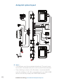
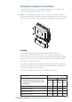
Autopilot computer installation
The autopilot computer is designed to operate in a location with
ambient temperatures below +55°C (+130°F).
¼ Note: The autopilot computer units (AC12N and AC42N) should be
mounted vertically in a place between the control unit and the drive
unit. The unit should not be exposed to dripping or splashing water.
Cabling
Use only shielded cables and ready made NMEA 2000 (or
compatible) cables and accessories. This includes motor supply,
drive unit cables and, if necessary, extension of the optional rudder
feedback cable(s). The clutch/bypass cable and the solenoid cable
should be 1.5 mm
2
(AWG14).
The motor supply cable and the drive unit motor cable should have
sufficient wire gauge. This will minimize voltage drop and allow the
drive unit to operate at full power.
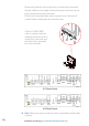
Refer to the table below for recommended cable sizes.
Cable length Drive unit voltage
1. Breaker panel to autopilot computer.
2. Autopilot computer to drive unit
motor (Length refers to each of the
two cables)
12 V 24 V
AWG mm
2
AWG mm
2
Up to 3 m (10 ft.) 12 2.5 12 2.5
Up to 6 m (20 ft.) 10 4 10 2.5
Up to 10 m (32 ft.) 8 6 10 4
Up to 16 m (52 ft.) 6 10 8 6