
Installation manual


Interfacesandintegration
ConnectthegroundwiretooneoftheGroundpins(18-22).
Slavesystem
Ifanexternalsystemisusedtoprovidethetransmittrigger,thetriggersignalmustbe
connectedtooneoftheTrigIninputsonthetransceiver’sAuxiliaryconnector.When
activated.thetriggersignalfromtheexternalsystemwillallowtheES70systemto
transmit.
IfmorethanonetransceiverisusedbytheSlavesystem,theinputtriggermustbe
connectedtoallthetransceiversinparallel.
TwoTrigIninputsareavailableforeitherpositiveornegativetriggering.TheTrigIn-
inputissensitivetoahigh-to-lowtransition.
ConnectthegroundwiretooneoftheGroundpins(18-22).
GPTAuxiliaryplugschematics
Thecircuitryprovidinginputandoutputtriggering–aswellasotherinterfaces–are
providedintheschematicsbelow.
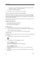
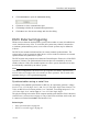
Figure17Digitalinput
10k
+5Vdc
39,2k
C C
U1
(CD010010A)
Thisdigitalinputcircuitryisvalidforthefollowinginterfaces:TrigIn+,TrigIn-,Event
andLog.
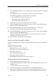
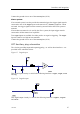
Figure18Digitaloutput
100k
+5Vdc
BSR14
(CD010010B)
Thisdigitaloutputcircuitryisvalidforthefollowinginterfaces:TrigOut+,TrigOut-
andAlarm.
343522/A
97