
Installation manual
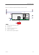

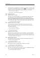

ES70Cablelayout
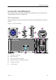
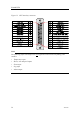
Transducerconnections
Transducertypes
Theechosoundercanbeusedwithalargevarietyoftransducers.Thelargetransducer
connectorontheGeneralPurposeTransceiverUnit(GPT)hasbeenpreparedtoaccept
allofthem,providedthattheappurtenantcircuitboardsarettedtotheunit.The
followingtransducertypesmaybeused:
•Singlefrequency,singlebeam(highorlowpower)
•Singlefrequency,dualbeam(wideornarrow)
•Singlefrequency,splitbeam
Transducercables
Forthemajorityofthetransducers,thecablesaresuppliedbySimrad.Theseare
normallyphysicallyfastenedtothetransducer.
Note
ThedistancebetweentheGeneralPurposeTransceiverandthetransducer(s)mustbeas
shortaspossibletoavoidinterferenceandnoise.
Alltransducercablesmustberuninsteelconduits.Cableshieldsmustbeconnected
totheplughousing.
Ifthedistancebetweenthetransducerandthetransceiverexceedsthelengthofthecable,
ajunctionboxmustbeused.Thecablebetweenthejunctionboxandthetransceivermust
thenbesuppliedbySimrad,andthismustbethesametypeasusedonthetransducer(s).
Transducercablesplicing
Ifyouneedtocutorlengthenthetransducercable,youmustspliceitcorrectly.The
cablebetweenthejunctionboxandthetransceivermustthenbesuppliedbySimrad,
andthismustbethesametypeasusedonthetransducer(s).Tosplicethecable,usea
metaljunctionboxwithEMCcableglandsandaterminalblock.Theterminalblock
mustprovidesolidfasteningofthecableendsaswellassufcientinsulationbetween
thewires.Werecommendthatthecablescreenisconnectedtothejunctionboxchassis
usingtheEMCcableglands,butifyoudothis,thejunctionboxchassism
u s t n o t be
connectedtovessel’sground.
Note
D o n o t solderthewirestogetherwithonlyelectricaltapeforinsulation.Thiswillresult
inelectricalnoiseandreducedoperationalperformance.
D
o n o t connectthecablescreentothevessel’ sground.
Transducerconnectiondrawings
•Singlebeam/normalpowertransduceronpage64
343522/A
37