
Installation manual

SimradES70
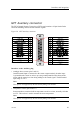
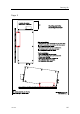
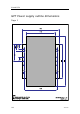
•Supplyvoltages(output)
–Pin5:+12Vdc,max100mA(Groundonpin18)
–Pin6:-12Vdc,max100mA(Groundonpin19)
–Pin7:+5Vdc,max200mA(Groundonpin20)
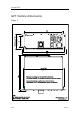
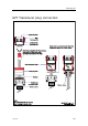
•Transmitsynchronisation(pins12,13,23,24and25)
–TrigInandTrigOutaredigitalsignalsprovidedfortransmitsynchronisationwith
externalequipmentofvariousmakes.
–TrigOut+isnormallylow,andTrigOut-isthelogicalinverseofTrigOut+.
–Ininternaltriggermode,TrigOut+goeshigh(outputtransistorisnotconducting)
whenthetransmitpulsestarts,anditgoeslowagainwhenallfrequencychannels
withinthetransceiverhavenishedtransmitting.TheTrigInsignalsaretotally
disregarded.
–Inexternaltriggermode,transmissionisdelayeduntilapulseisdetectedatone
oftheTrigIninputs;alow-to-hightransitionattheTrigIn+inputorahigh-to-low
transitionattheTrigIn-input.TrigOut+goeshighwhenthetransceiverisreadyto
transmit,anditgoeslowagainwhenallfrequencychannelswithinthetransceiver
havenishedtransmitting.
–TheRemoteInsignalatpin23switchesthetransceiveron/off.Leftopenthe
transceiverison.Ifgrounded(lessthan+2.5Vdc)thetransceiverisoff.
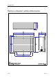
•Eventin
Useasimplenon-lockingpush-to-makeswitchtotriggeranevent.Averticallineis
drawnontheechogram
Note
ThisinputisnotsupportedbytheES70Fishndingechosounder.
•Alarmout
Apositive(+5Vdc)levelisprovidedwhenthealarmisenable.
Note
Notethatthisoutputm u s t n o t beusedtopowerlamps,speakersorsounderdirectly.
Thealarmsignalm
u s t beconnectedtoanopto-coupler,arelayorasimilardeviceto
powerperipheralalarmunits.
Note
ThisoutputisnotsupportedbytheES70Fishndingechosounder.
Relatedtopics
•GPTremoteon/offonpage56
•GPTtrigger/synchronisationonpage58
100
343522/A