
Installation Manual: 22.8kWh


SimpliPhi Power, Inc. | 3100 Camino Del Sol | Oxnard, CA 93030, USA | (805) 640-6700 | info@simpliphipower.com | SimpliPhiPower.com
| 21 |
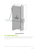
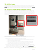
Figure 11.0 a– Four PHI Battery Orientation
4. Attach interconnecting busbars onto the batteries’ terminals. Each positive busbar parallels one set of
two or three batteries (positive to positive to positive), and each negative busbar parallels one set of
two or three batteries (negative to negative to negative). 2 battery interconnecting busbars utilize a
31", 2 AWG cable. 3 battery inconnecting busbars utilize a 25", 2/0 cable.
5. Secure the busbars to the batteries’ terminals using a 11/16” wrench socket to tighten the 3/8” lock
washers and 11/16” stainless steel hex nuts (originally included on the batteries). Tighten the nuts to
160 in-lbs.
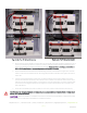
6. Connect the included cables from the interconnecting busbars (secured to the batteries) to the 5-
point terminal busbars (see above). All connections are in parallel: each positive cable connects from
each interconnecting positive busbar to the positive 5-point terminal busbar, and each negative cable
connects from each negative busbar to the negative 5-point terminal busbar (refer to Figure 11.0a
and 11.0b above).
7. Leave the PHI 3.8 batteries’ built-in breakers in the “OFF” position until the basic functional test.
The PHI batteries’ charging regimen is not temperature compensated; do not include a Battery Temperature
Sensor (BTS) wiring connection.
CAUTION: Adhere to all battery installation instructions as outlined in the PHI Battery Installation Manual;
this manual does not substitute the PHI Battery Installation Manual.
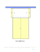
Figure 11.0b
– Five PHI Battery Orientation
REV20210319