
A-4PHI-OB Installation


REV0720
18
SimpliPhi Power, Inc. | 420 Bryant Circle | Ojai, CA 93023, USA | (805) 640-6700 | info@simpliphipower.com | SimpliPhiPower.com
| 14 |
greatest efficiency and freedom from material impurities, toxicity and hazardous risk. They do not
contain cobalt.
Each PHI 3.5 Battery contains circuitry that protects the Lithium Ferrous Phosphate cells from
overcharge, over-discharge and excessive load amperage. If the values specified are exceeded,
the protective circuitry will shut down the flow of electricity to/from the PHI 3.5 Batteries. In some
cases, this will result in the need to re-initialize an inverter charger. Each AccESS unit is
programmed to avoid such a situation, barring abnormal conditions beyond the designed
parameters and Warranty terms. If low voltage incidents do occur, the inverter settings will be
saved within the inverter memory storage and will not need to be reset.
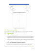
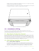
4.2.2 – Battery Bank Installation
After mounting the AccESS unit on concrete, place 4 PHI 3.5 Batteries in the bottom of the
cabinet. Connect the Battery Cable that is pre-wired into the GS Load Center to the positive and
negative terminals of each PHI 3.5 Battery per the torque values in the next section. Leave the
PHI 3.5 Batteries in the “OFF” position until the basic functional test.
CAUTION: PHI 3.5 Batteries must be fully charged before commissioning the AccESS unit. Failure to do
so will void the Warranty.
CAUTION:
Verify polarity at all connections before energizing system. Reverse polarity at the PHI 3.5
Battery terminals will void the Warranty and destroy the PHI 3.5 Batteries.
CAUTION:
Solid Blue Wire = Negative Lead
Blue with Red Stripe = Positive Lead
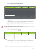
4.3 – Torque Values
For the DC terminals on the PHI 3.5, torque bolts to 160 in-lbs (13.3 ft-lb).
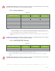
4.4 – Communications and Network Preparation
Communication and Monitoring is available via the included Mate 3 through the OpticsRE network. A
wireless router as well as onsite internet/wifi is required.
OPTICS RE is the web-based remote monitoring and control application for OutBack devices.
• The OPTICSre menu item enables or disables the application.
• It is also possible to communicate with OutBack devices using the Modbus protocol and SunSpec
client software as described in OutBack AXS Port Owner’s Manual. The SunSpec Interface
menu item enables or disables this type of data stream from the MATE3
• The Modbus Port menu item is the Modbus TCP/IP port number. The default settings is the
standard internet designation. The port number can be changed if necessary.
• OPTICS RE allows you to view system health, settings, and make adjustments to programming
within the connected devices
For OPTICS RE configuration, please see the OutBack Power’s documentation on MATE 3 configuration.
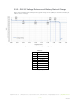
4.5 – Wiring the AccESS
For Wiring information please refer to the OutBack GSLoad Center installation manual
http://www.OutBackpower.com/downloads/documents/inverter_chargers/radian_gs_load_center/gs_loadc
enter_install.pdf