
Schneider Electric Integration Guide

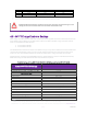
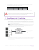
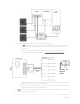
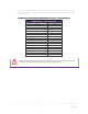
Table Of Contents

REV20201
222
SimpliPhi Power, Inc. | 3100 Camino Del Sol | Oxnard, CA 93030, USA | (805) 640-6700 | info@simpliphipower.com | SimpliPhiPower.com
| 8 |
•
2.
Per PHI 3.8 kWh 48V battery – These settings are calculated by multiplying the nominal value per-battery value times
the # of batteries. For other batteries, refer to the Warranty and Specification Sheet for the specific model. Refer to
Charge Controller Bank Sizing under the “Battery Bank Sizing” section.
•
3.
To calculate Max Charge Rate as a percentage, divide the calculated Max Bulk Current in Amps DC by the equipment’s
maximum potential charging current:
Bat QTY PHI 3.8 / 24V
(45ADC)
1 x MPPT 80
(80ADC charger)
PHI 3.8 / 48V
(37.5ADC)
1 x MPPT 80 (80ADC
charger)
2
90A
100%
75A
93%
• Levels are typical @ 25⁰C and may need adjusting at temperature extremes.
• When performing rapid deep charge/discharge cycles the battery should be allowed to "rest" 15 minutes in between.
• Always refer to the SimpliPhi Power Manual and Warranty for the specific PHI battery model.
CAUTION: When PHI battery quantities change, the capacity & charge/discharge current
settings must be reassessed. Failure to do so will void the Warranty.
4.4 – Conext Battery Monitor Wiring & Settings
The Schneider Electric Conext
TM
Battery Monitor determines the connected battery bank’s state of charge
(SOC). For the Battery Monitor to operate properly, adhere to the following wiring instructions:
1. The battery monitor involves the routing of the system’s DC Negative wires “through” a battery
shunt. On the shunt, one side is designated as the battery bank’s connection point and the other
side is designated as the system’s connection point. The system connection point includes wiring
from the inverter and charge controller(s).
Note: All DC Positive wiring is wired as usual; follow SimpliPhi and Schneider Electric’s relevant
installation manuals for DC Positive wiring instructions.
2. IF the PHI batteries are paralleled in a battery box, or using bussing directly on the batteries’
terminals, wire the battery bank to the battery shunt like so:
3. IF the PHI batteries are paralleled in the Schneider Conext’s Power Distribution Panel (PDP), then
the inverter and charge controller(s) negative wiring must land directly on the shunt’s “system”
connection point, like so:
to Conext XW+ PDP
or Mini PDP’s DC
Negative Busbar