
Schneider Electric Integration Guide
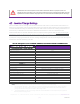
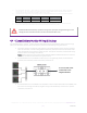
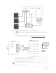
Table Of Contents

REV20201
222
SimpliPhi Power, Inc. | 3100 Camino Del Sol | Oxnard, CA 93030, USA | (805) 640-6700 | info@simpliphipower.com | SimpliPhiPower.com
| 4 |
1.0 – Introduction
This integration guide covers the recommended set up and configuration of Schneider Electric equipment for
optimizing performance with SimpliPhi PHI 3.8 kWh batteries. More information on SimpliPhi products can be
found on our website: https://simpliphipower.com/
.
Schneider Electric offers many products which are too numerous to be covered here. The specific Schneider
products covered in this guide include, but are not limited to:
• Schneider Conext XW+ Inverter/Chargers
o Conext XW Pro
o Conext XW+ 6848 NA
o Conext XW+ 5548 NA
• Schneider Conext MPPT Charge Controllers
o Conext MPPT 60 150
o Conext MPPT 80 600
• Schneider Conext Battery Monitor
2.0 – Charge Controller and Inverter Settings
Schneider Electric has performed qualification testing of the PHI 3.8 kWh battery with their equipment. Based
on these combined tests and evaluations, the following parameters (refer to table below) have been
established. More information on Schneider Electric products can be found on their website:
https://solar.schneider-electric.com/
.
3.0 – Battery Bank Sizing
A properly sized PHI battery bank should be sized to prevent any risk of over-discharge or over-charge.
Depending on the specifications of the equipment used in the system, sizing the PHI battery bank based on
these two criteria may yield different results. Therefore, the best practice is to calculate the PHI battery bank
based on both criteria and use the greater of the two results as the minimum quantity. We can compare these
two calculation methods assuming the nomenclature below:
• Battery rated continuous power = Bat
kW
• Inverter power full load = Inv
kW
• Inverter efficiency = Inv
eff
• Maximum battery charge current = I
BatChrgMax
• PV charge controller maximum = I
PVChrgMax
• Recommended minimum number of batteries = B
#
Discharge equation: B
#Inv
≥ Inv
kW
/ Inv
eff
/ Bat
kW
Charge equation: B
#PV
≥ I
PVChrgMax
/ I
BatChrgMax
3.1 – Discharge Calculation: Inverter Power Bank Sizing
To protect against over-discharge (voiding the battery Warranty), the PHI battery bank should be sized to
handle the inverter’s “load rate”: the amount of power that is potentially discharged from the battery bank to
the loads.
Discharge Example: B
#Inv
≥ Inv
kW
/ Inv
eff
/ Bat
kWh
• Inverter is rated at 6.8 kW
• Inverter efficiency is 92.5%
• PHI 3.8 kWh-51.2V
nom
battery is rated at 1.9 kW MAX Continuous Discharge Rate