
Schneider Electric Integration Guide
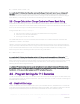
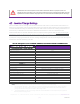
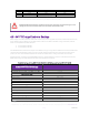
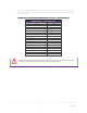
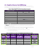
Table Of Contents

REV20201
222
SimpliPhi Power, Inc. | 3100 Camino Del Sol | Oxnard, CA 93030, USA | (805) 640-6700 | info@simpliphipower.com | SimpliPhiPower.com
| 11 |
4.4 – Conext Auto Generator Start (AGS) Settings
The Schneider Electric Conext
TM
Auto Generator Start (AGS) device allows for a connected generator to
automatically start and stop according to battery voltage. Check with your generator manufacturer regarding
the compatibility of your generator with this AGS device.
Table 4.0 – Settings for SimpliPhi PHI 3.8 kWh 48V Battery w/Schneider Conext AGS
Conext AGS Settings
Advanced Settings > Cfg Trigger
80% DoD
90% DoD
100% DoD
Start DCV 30 sec
50.4V
49.8V
48.2V
Start DCV 15 min
Disabled
Start DCV 2 hr
Disabled
Start DCV 24 hr
Disabled
Stop Float
Enabled
Stop Absorb
Disabled
Stop V
Disabled
Temp1
Disabled
Temp2
Disabled
Load
Enabled if necessary
1
Strt Load
See Table 5.0
Stop Load
(Start Load Value) – 1A
Load Start Delay 0 s
Start Soc
20%
Stop Soc
90%
• 1. Enable the Load trigger if the battery bank does not meet the Power Bank Sizing requirements outlined in Section 3.1.
The Start Load trigger enables the generator to start at a specified AC load (current draw) on the inverter. The
current draw must be present for 5 minutes before the generator will start. The generator will assist the
inverter with powering the AC load.
If the inverter(s’) power rating exceeds the battery bank’s maximum instantaneous discharge rating (i.e. does
not adhere to the sizing requirements outlined in Section 3.1 above), enable the
Load start trigger to prevent
the battery bank from over-discharging through the inverter to the loads.
1. First convert DC discharge current to DC watts. (AC and DC watts are the same)
2. Then apply the inverter efficiency.
3. Then convert AC watts to AC current.
Table 5.0 – Conversion from DC to AC Limit for 1 to 5 PHI 3.8 kWh 48V Batteries (37.5A DC limit per PHI battery)
A
B
C
D
E
F
# of Parallel
Batteries
DC Current
Limit
ADC x VDC (48)
WDC ÷ Inverter
Efficiency (90% = .9)
Column D ÷ Inverter
Voltage (120 or 240
VAC, dep. on inverter;
240 VAC used below)
Round down (only
whole #s can be used
as input)
1
37.5A
1,800 WDC 2,000 WAC 8.33 AAC
**
2
75A
3,600 WDC 4,000 WAC 16.67 AAC
16 AAC
3
112.5A
5,400 WDC 6,000 WAC 25 AAC
25 AAC
4
150A
7,200 WDC 8,000 WAC 33.33 AAC
33 AAC
5
187.5A
9,000 WDC 10,000 WAC 41.67 AAC
41 AAC
**10A is the minimum programmable value