Power. On Your Terms. SimpliPhi Power PHI Battery INTEGRATION GUIDE: OUTBACK POWER INSTALLATION MANUAL Optimized Energy Storage & Management for Residential & Commercial Applications Utilizing Efficient, Safe, Non-Toxic, Energy Dense Lithium Ferrous Phosphate (LFP) Chemistry © SIMPLIPHI POWER, INC.
SimpliPhi Your Energy Security and Independence and gain control of your own power. SimpliPhi helps you manage your power as a personal resource. Anytime. Anywhere. SimpliPhi energy storage optimizes integration of any power generation source – solar, wind, generator – on or off grid and protects your home and missioncritical business functions from power outages and intermittency.
Table of Contents 1.0 – Introduction ..................................................................................................................... 4 2.0 – Charge Controller and Inverter Settings........................................................................ 4 3.0 – Battery Bank Sizing......................................................................................................... 4 3.1 – Discharge Calculation: Inverter Power Bank Sizing ..............................................
1.0 – Introduction This integration guide covers the recommended set up and configuration of Outback Power equipment for optimizing performance with SimpliPhi PHI 3.8 kWh batteries. More information on SimpliPhi products can be found on our website: https://simpliphipower.com/. Outback Power offers many products which are too numerous to be covered here.
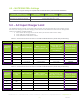
3.2 – Charge Calculation: Charge Controller Power Bank Sizing To optimize solar harvesting, a properly sized PHI battery bank should be able to accept the maximum PV charge current. To determine the minimum number of batteries required to optimize PV, divide the output of the charge controller(s) by the “max continuous charge current” per PHI Battery. Be sure to verify the “max continuous charge current” for the PHI battery model that you’re using, because it may differ from C/2 depending on the model.
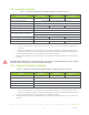
4.2 – Inverter Settings Table 1.0 - Settings for SimpliPhi PHI 3.8 kWh 48V Battery w/Outback Inverters Inverter Settings Absorb Voltage (V), Time Float Voltage and Time 10k Cycles (80% DOD) 5k Cycles (90% DOD) 3.5k Cycles (100% DOD) 27.2 / 54.4, 1 hour 27.2 / 54.4, 1 hour 28 / 56, 1 hour N/A (disable float by setting Float Time to 0) Refloat Voltage Re-Bulk Voltage N/A (disable float) 25.4 / 50.8 AC Input Mode 25.3 / 50.
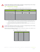
CAUTION: When PHI battery quantities change, the capacity & charge/discharge current settings must be reassessed. Failure to do so will void the Warranty. 4.4 – FLEXnet DC Settings Table 3.0 - Settings for SimpliPhi PHI 3.8 kWh 48V Battery w/Outback FLEXnet DC 10k Cycles (80% DoD) FLEXnet DC Settings 5k Cycles (90% DoD) FNDC Battery Ah1 151Ah / 75Ah FNDC Charged Voltage (V) FNDC Charged Return 3.5k Cycles (100% DoD) 27.0 / 54.0 27.0 / 54.0 Amps1 27.8 / 55.
4.5 – MATE3/MATE3s Settings Table 5.0 - Program Settings for SimpliPhi PHI 3.8 kWh 48V Battery w/Outback MATE3/MATE3s MATE3 / MATE3s Settings 10k Cycles (80% DoD) 5k Cycles (90% DoD) 3.5k Cycles (100% DoD) FLEXnet DC Advanced Control Low SOC Warning = 20% FLEXnet DC Advanced Control Critical SOC Warning = 10% 5.
Example - Using the max DC charge current of 45 amps in a 24V system: 1. Multiply the charge current by the voltage: 45 Adc x 24 Vdc = 1,080 Wdc 2. Divide this by the charger efficiency (85% = 0.85): 1,080 Wdc ÷ 0.85 = 1,270 Wac 3. Divide this by the inverter voltage (120 or 240 Vac depending on inverter): 1,270 Wac ÷ 240Vac = 5.29 Aac 4.