
MidNite Solar Integration Guide

REV070219
SimpliPhi Power, Inc. | 3100 Camino Del Sol | Oxnard, CA 93030, USA | (805) 640-6700 | info@simpliphipower.com | SimpliPhiPower.com
| 4 |
1.0 – Introduction
This Integration Guide is intended to supplement the PHI Battery and Midnite Solar Installation Manuals.
It covers the recommended set up and configuration of Midnite Solar Charge Controller equipment for
optimizing performance with SimpliPhi PHI 3.8 kWh batteries. More information on SimpliPhi products can
be found on our website: https://simpliphipower.com/.
SimpliPhi Power offers solutions for a range of Midnite Solar products covering 24V to 48V PHI battery
applications, which are too numerous to be covered here. If the Midnite Solar product you are looking for
is not covered in this Integration Guide, the parameters listed here should be used as a general guide.
The specific Midnite Solar products covered in this guide include, but are not limited to:
• Midnite Solar Classic charge controllers
o Midnite Solar Classic 150, 200 & 250
o Midnite Solar Classic 150, 200 & 250 LITE
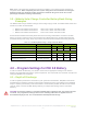
2.0 – Charge Controller Settings
Based on tests and evaluations of the PHI 3.8 kWh battery with Midnite Solar’s equipment, the following
parameters (refer to table below) have been established. More information on Midnite Solar Classic
series charge controller products can be found on their website:
http://www.midnitesolar.com/documentIndex.php.
3.0 – Battery Bank Sizing
A properly sized PHI battery bank should be sized to handle the maximum potential solar array output.
The following calculation method assumes the nomenclature below:
• Maximum battery charge current = I
BatChrgMax
• PV charge controller maximum = I
PVChrgMax
• Recommended minimum number of batteries = B
#
Charge equation: B
#PV
≥ I
PVChrgMax
/ I
BatChrgMax
3.1 – Charge Calculation: Charge Controller Power Bank
Sizing
To optimize solar harvesting, a properly sized PHI battery bank should be able to accept the maximum
PV charge current. To determine the minimum number of PHI batteries required to optimize PV, divide
the output of the charge controller(s) by the “max continuous charge current” per PHI battery. Be sure to
verify the “max continuous charge current” for the PHI battery model that you’re using, because it may
differ from C/2, depending on model.
Charge Example: B
#PV
≥ I
PVChrgMax
/ I
BatChrgMax
• Max continuous charge current for PHI 3.8 kWh 48V = 37.5A
• PV charge controller max = 86A
B
#PV
≥ 86A / 37.5A = 2.29
A properly sized PHI battery bank based on available PV charge would have a minimum of 3
batteries. This maximizes the use of available PV while ensuring the batteries are never stressed by
overcharging. If the PHI battery bank has fewer batteries than calculated, special care must be taken with
the charge controller settings to limit the charge rate below the specified rating of the PHI battery. These
settings are described in the following sections of this Integration Guide.