
Outback Power Integration Guide
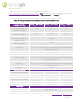
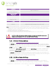
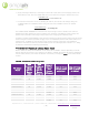
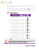
Table Of Contents

REV042920
SimpliPhi Power, Inc. | 3100 Camino Del Sol | Oxnard, CA 93030, USA | (805) 640-6700 | info@simpliphipower.com| SimpliPhiPower.com
| 15 |
batteries exceed the
DoD Volts
setting by 0.8 Vdc or more, the Radian will send power from the batteries
to the loads. As the battery voltage decreases to the
DoD Volts
setting, the inverter will reduce the rate
of flow toward zero and loads will be powered by the grid. It will maintain the batteries at this setting
until renewable sources recharge the batteries.”
Remember, the programmed Re-Bulk Voltage in the inverter is ignored while in Grid Zero mode because
the inverter’s charger is off. In this mode, the batteries charge only from the renewable energy source via
the connected charge controller(s).
“When
DoD
Volts
is set low, this mode allows more renewable energy to be delivered from the batteries
to the loads. However, it will also leave less battery reserve in the event of a grid failure.”
By programming Grid Zero
DoD Volts
to 50V, the Radian inverter will begin curtailing the batteries’
discharge at 50.8V. Setting
Grid Zero
DoD Volts
to 50V is the lowest permitted value while still
maintaining the PHI Batteries’ ~80% maximum DoD.
“When
DoD Volts
is set high, the batteries will not be discharged as deeply and will retain more of a
backup reserve. However, not as much renewable energy will be sent to the loads.”
By programming Grid Zero
DoD Volts
to 51.6V, the Radian inverter will begin curtailing the batteries’
discharge at 52.4V, nearly 100% Sate of Charge (SoC). It would not make sense to program
Grid Zero
DoD Volts
to a value higher than 51.6V.
Refer to the Battery Voltage VS. SoC Table at the end of this document for further guidance.
According to the OutBack Radian Series Inverter/Charger Operator’s Manual:
“To prolong cycle life and increase battery capacity, the rate of discharge can be limited using the
DoD
Amps
setting. This item should be set lower than the current provided by the renewable source.”
Refer to the Charger AC Limit Table for the maximum permissible Amps AC — charge or discharge — per
battery.
4.2.3 – Radian Charger AC Limit Calculation
The OutBack Radian inverter/charger’s Charger Limit setting is regulated on the AC input side of the
charger (not the DC side of the charger). Convert the PHI Battery bank’s maximum* continuous DC
charging current to the charger’s AC current limit by following these steps:
1. Convert the PHI Battery bank’s maximum continuous DC charging current to DC watts.
2. Apply the charger efficiency.
3. Convert AC watts to AC current.
*When Grid charging specifically, it is permissible to charge the battery bank according to its maximum continuous DC charging
current, but SimpliPhi recommends charging at less than the maximum current. In a Grid charging scenario, multiply the Charging
Amps found according to this section by 40% or less.
Example: Four PHI 3.8 kWh-51.2V
nominal
batteries (used in a 48-Volt system) are paired with an OutBack
Radian GS8048A model inverter/charger.
1. Each PHI 3.8 kWh-51.2V battery has a maximum continuous DC charging current of 37.5 Amps DC,
or 1,920 Watts DC at the battery’s 51.2 nominal voltage. The four-battery bank has a combined
maximum continuous DC charging current of 150 Amps DC, or 7,680 Watts DC.
= ×
1,920 = 37.5 × 51.2
7,680 = 4 × 37.5 × 51.2