Power. On Your Terms. SimpliPhi Power PHI Battery INTEGRATION GUIDE: MAGNUM ENERGY INSTALLATION MANUAL Optimized Energy Storage & Management for Residential & Commercial Applications Utilizing Efficient, Safe, Non-Toxic, Energy Dense Lithium Ferrous Phosphate (LFP) Chemistry © SIMPLIPHI POWER, INC.
SimpliPhi Your Energy Security and Independence and gain control of your own power. SimpliPhi helps you manage your power as a personal resource. Anytime. Anywhere. SimpliPhi energy storage optimizes integration of any power generation source – solar, wind, generator – on or off grid and protects your home and missioncritical business functions from power outages and intermittency.
Table of Contents 1.0 – Introduction ..................................................................................................................... 4 2.0 – Charge Controller and Inverter Settings........................................................................ 4 3.0 – Battery Bank Sizing......................................................................................................... 5 3.1 – Discharge Calculation: Inverter Power Bank Sizing...............................................
1.0 – Introduction This integration guide covers the recommended set up and configuration of Magnum Energy equipment for optimizing performance with SimpliPhi PHI 3.8 kWh batteries. More information on SimpliPhi products can be found on our website: https://simpliphipower.com/. Magnum Energy offers many products which are too numerous to be covered here.
3.0 – Battery Bank Sizing A properly sized PHI battery bank should be at least double (2x) the kW rating of the inverter(s) and have a C/2 rating greater than the maximum charge controller rating. Depending on the specifications of the equipment used in the system, sizing the PHI battery bank based on these two criteria may yield different results. Therefore, the best practice is to calculate the PHI battery bank based on both criteria and use the greater of the two results as the minimum quantity.
3.1 – Discharge Calculation: Inverter Power Bank Sizing To optimize the PHI battery bank and protect against over-discharge and voiding the battery Warranty, the PHI battery bank should be sized at least double (2x) the kW rating of the inverter. Discharge Example A This example uses the following calculation: B#Inv ≥ InvkW / BatkW This example assumes the following: • Inverter is rated at 4.4 kW • PHI 3.8 48V battery has a load rating of 1.92 kW (37.5 Amps DC x 51.
3.2 – Charge Calculation: Charge Controller Power Bank Sizing To optimize solar harvesting, a properly sized PHI battery bank should be able to accept the maximum PV charge current. To determine the minimum number of PHI batteries required to optimize PV, divide the output of the charge controller(s) by the “max continuous charge current” per PHI battery. Be sure to verify the “max continuous charge current” for the PHI battery model that you’re using, because it may differ from C/2 depending on the model.
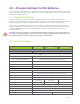
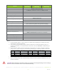
4.0 – Program Settings for PHI Batteries In order to maintain the Warranty, it is critical to ensure that the appropriate settings for the desired Warranty are programmed in all of the system components. This section will cover the basic concepts and settings for Magnum Energy equipment. 4.
General 10k Cycles (80% DOD) Disconnect Volts4 5k Cycles (90% DOD) 27.2V / 54.4V 3.5k Cycles (100% DOD) ME-BMK is required for this setting The 02D AC In – VDC setting is preferred over 02E AC In - SOC 02E AC In – SOC Connect SOC 20% Disconnect SOC 100% 02F Power Up Always OFF 03 Charger Setup 03C Battery Type CC/CV 45A per PHI3.8 24V Max Charge Amps1 (ADC) CV Charge Volts (VDC) CV Chg Done Time CV Chg Done Amps (ADC) 37.5A per PHI3.8 48V 27.2V / 54.
4.3 – MPPT Charge Controller Settings Solar charge controllers must be used in DC coupled systems to regulate the power produced by the PV array that is delivered to the batteries. Magnum Energy offers one MPPT charge controller, the PT-100, which is compatible with PHI batteries: SETUP 06 PT Setup 06A Battery Type Custom Absorb Volts 27.2V / 54.
4.4 – Auto Generator Start (AGS) Settings Verify with Magnum Energy and your generator manufacturer regarding your generator’s compatibility with Magnum’s AGS device. SETUP 04 AGS Setup AGS is required for this setting Verify AGS-generator compatibility with Magnum / Sensata 04A Gen Run VDC Start Gen Volts 25.2V / 50.4V Start Volts Delay Stop Gen 1 min Volts4 Stop Volts Delay 04C Gen Run Amps 27.2V / 54.
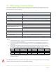
Table 2.0 – 04C Gen Run Amps 04C Gen Run Amps autostarts the generator based on the amount of AC amps needed to handle the load the inverter is running. A battery bank with a maximum continuous discharge rate greater than the inverter’s load rate does not need to utilize the 04C Gen Run Amps setting. For example, 4 x PHI 3.8 48V batteries paired with 1 x Magnum MS 4448 PAE run no risk of overdischarging to power the instantaneous load: • Max. continuous discharge current for 4 x PHI 3.8 48V = 4 x 37.
4.6 – Recharge Voltage Adjustment The Recharge setting often acts as the trigger in which a new charge cycle will start. The standard voltage set point is 50.5V, as per the manual; however, you can adjust this setting to fit the application in which the battery is being used. The following table shows battery voltage correlated with State of Charge (SOC). Table 7.0 – Correlating Battery Voltage to State of Charge SOC Voltage 48V Voltage 24V 100% >52.5 >26.2 95% 51.7 25.9 90% 51.6 25.8 75% 51.
5.0 – Specifications & Warranty For your reference: • • See PHI 3.8 kWh Specifications sheet. See PHI 3.8 kWh 10-Year Warranty; Failure to adhere to installation protocol will void Warranty. 6.0 – SimpliPhi Technical Support For technical support related to your PHI 3.8 kWh 48V Battery (or other SimpliPhi Power products), please contact us directly at: 805.640.6700 techsupport@simpliphipower.com SimpliPhi Power, Inc. | 3100 Camino Del Sol | Oxnard, CA 93030, USA | (805) 640-6700 | info@simpliphipower.