Power. On Your Terms. SimpliPhi Power PHI Battery INTEGRATION GUIDE: OUTBACK POWER Optimized Energy Storage & Management for Residential & Commercial Applications Utilizing Efficient, Safe, Non-Toxic, Energy Dense Lithium Ferrous Phosphate (LFP) Chemistry © SIMPLIPHI POWER, INC.
SimpliPhi Your Energy Security and Independence and gain control of your own power. SimpliPhi helps you manage your power as a personal resource. Anytime. Anywhere. SimpliPhi energy storage optimizes integration of any power generation source – solar, wind, generator – on or off grid and protects your home and missioncritical business functions from power outages and intermittency.
Table of Contents 1.0 – Introduction ..................................................................................................................... 4 2.0 – Charge Controller and Inverter Settings ........................................................................ 4 3.0 – Battery Bank Sizing......................................................................................................... 4 3.1 – Discharge Calculation: Inverter Power Bank Sizing .............................................
1.0 – Introduction This integration guide covers the recommended setup and configuration of Outback Power equipment for optimizing performance with SimpliPhi PHI 3.5 kWh batteries. More information on SimpliPhi products can be found on our website: http://simpliphipower.com/. Outback Power offers many products which are too numerous to be covered here.
3.2 – Charge Calculation: Charge Controller Power Sizing To optimize solar harvesting, a properly sized PHI battery bank should be able to accept the maximum PV charge current. To determine the minimum number of batteries required to optimize PV, divide the output of the charge controller(s) by the “max continuous charge current” per PHI Battery. Be sure to verify the “max continuous charge current” for the PHI battery model that you’re using, because it may differ from C/2 depending on the model.
4.2 – Inverter Settings Table 1.0 - Settings for SimpliPhi PHI 3.5 kWh 24V and 48V Battery w/Outback Inverters Inverter Settings Absorb Voltage (V), Time 10k Cycles (80% DOD) 5k Cycles (90% DOD) 3.5k Cycles (100% DOD) 27.8 / 55.4, 0.1 hour 28.4 / 57.2, 0.1 hour 28.4 / 57.2, 0.1 hour Float Voltage and Time N/A (disable float) Refloat Voltage N/A (disable float) Re-Bulk Voltage 25.3 / 50.
4.4 – FLEXnet DC Settings Table 3.0 - Settings for SimpliPhi PHI 3.5 kWh 48V Battery w/Outback FLEXnet DC FLEXnet DC Settings 10k Cycles (80% DoD) FNDC Battery Ah1 FNDC Charge Voltage (V) 5k Cycles (90% DoD) 3.5k Cycles (100% DoD) 138Ah / 69Ah 27.6 / 55.2 28.2 / 57 FNDC Charged Return Amps 8A / 4A FNDC Battery Charge Factor 98% FNDC Relay Invert Logic 28.2 / 57 No FNDC Relay Voltage High/Low High = 26.5/53, Low = 28.8/49.
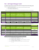
5.0 – AC Input Charger Limit The Outback inverter charger current limit setting is made from the AC input side of the charger (not the DC side of the charger) so the AC charging current must be calculated then entered as the charger limit setting. Per Outback recommendations: 1. First convert DC charge current to DC watts. (AC and DC watts are the same) 2. Then apply the charger efficiency. 3. Then convert AC watts to AC current. Table 5.0 – Conversion from DC to AC Limit for 1 to 5 PHI 3.
CAUTION: This calculation is for a single PHI battery, and can be increased proportionately with the total number of batteries in parallel. i.e. Setting for Aac using three 24V batteries is (5.29 x NBATTERIES = 15.88 Aac; round up to 16 Aac). 6.0 – Specifications & Warranty For your reference: See PHI 3.5 kWh Specifications sheet. See PHI 3.5 kWh 10-Year Warranty; Failure to adhere to installation protocol will void Warranty. 7.