
MidNite Solar Integration Guide

REV0411
18
SimpliPhi Power, Inc. | 420 Bryant Circle | Ojai, CA 93023, USA | (805) 640-6700 | info@simpliphipower.com | SimpliPhiPower.com
| 4 |
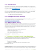
1.0 – Introduction
This Integration Guide is intended to supplement the PHI Battery and Midnite Solar Installation Manuals.
It covers the recommended set up and configuration of Midnite Solar Charge Controller equipment for
optimizing performance with SimpliPhi PHI 3.5 kWh batteries. More information on SimpliPhi products can
be found on our website: http://simpliphipower.com/
.
SimpliPhi Power offers solutions for a range of Midnite Solar products covering 24V to 48V PHI battery
applications, which are too numerous to be covered here. If the Midnite Solar product you are looking for
is not covered in this Integration Guide, the parameters listed here should be used as a general guide.
The specific Midnite Solar products covered in this guide include, but are not limited to:
• Midnite Solar Classic charge controllers
o Midnite Solar Classic 150, 200 & 250
o Midnite Solar Classic 150, 200 & 250 LITE
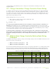
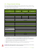
2.0 – Charge Controller Settings
Based on tests and evaluations of the PHI 3.5 kWh battery with Midnite Solar’s equipment, the following
parameters (refer to table below) have been established. More information on Midnite Solar Classic
series charge controller products can be found on their website:
http://www.midnitesolar.com/documentIndex.php
.
3.0 – Battery Bank Sizing
A properly sized PHI battery bank should be at least double (2x) the kW rating of the inverter(s) and have
a C/2 rating greater than the maximum charge controller rating. Depending on the specifications of the
equipment used in the system, sizing the PHI battery bank based on these two criteria may yield different
results. Therefore, the best practice is to calculate the PHI battery bank based on both criteria and use
the greater of the two results as the minimum quantity. We can compare these two calculation methods
assuming the nomenclature below:
• Battery rated continuous power = Bat
kWh
(typically @ C/2)
• Inverter power full load = Inv
kW
• Maximum battery charge current = I
BatChrgMax
• PV charge controller maximum = I
PVChrgMax
• Recommended minimum number of batteries = B
#
Discharge equation: B
#Inv
≥ Inv
kW
/ Bat
kWh
Charge equation: B
#PV
≥ I
PVChrgMax
/ I
BatChrgMax
3.1 – Discharge Calculation: Inverter Power Bank Sizing
To optimize the PHI battery bank and protect against over-discharge (voiding the battery Warranty), the
PHI battery bank should be sized at least double (2x) the kW rating of the inverter.
Discharge Example: B
#Inv
≥ Inv
kW
/ Bat
kWh
• Inverter is rated at 6.8 kW
• PHI battery is rated at 3.5 kWh, therefore the C/2 load rating is 1.75 kW
B
#Inv
≥ 6.8kW/1.75kW = 3.88
So, a properly sized PHI battery bank based on maximum discharge of the inverter would have a
minimum of 4 batteries. This ensures no greater than C/2 battery load. If the PHI battery bank has fewer
batteries than calculated, special care must be taken with the inverter settings to limit the load below the