Power. On Your Terms. SimpliPhi Power PHI Battery INTEGRATION GUIDE: MAGNUM ENERGY Optimized Energy Storage & Management for Residential & Commercial Applications Utilizing Efficient, Safe, Non-Toxic, Energy Dense Lithium Ferrous Phosphate (LFP) Chemistry © SIMPLIPHI POWER, INC.
SimpliPhi Your Energy Security and Independence and gain control of your own power. SimpliPhi helps you manage your power as a personal resource. Anytime. Anywhere. SimpliPhi energy storage optimizes integration of any power generation source – solar, wind, generator – on or off grid and protects your home and missioncritical business functions from power outages and intermittency.
Table of Contents 1.0 – Introduction ..................................................................................................................... 4 2.0 – Charge Controller and Inverter Settings........................................................................ 4 3.0 – Battery Bank Sizing......................................................................................................... 4 3.1 – Discharge Calculation: Inverter Power Bank Sizing...............................................
1.0 – Introduction This integration guide covers the recommended set up and configuration of Magnum Energy equipment for optimizing performance with SimpliPhi PHI 3.5 kWh batteries. More information on SimpliPhi products can be found on our website: http://simpliphipower.com/. Magnum Energy offers many products which are too numerous to be covered here.
3.1 – Discharge Calculation: Inverter Power Bank Sizing To optimize the PHI battery bank and protect against over-discharge and voiding the battery Warranty, the PHI battery bank should be sized at least double (2x) the kW rating of the inverter. Discharge Example This example uses the following calculation: B#Inv ≥ InvkW / BatkW This example assumes the following: • Inverter is rated at 4.4 kW • PHI 3.5 48V battery has a load rating of 1.74 kW (34 Amps DC x 51.
3.2 – Charge Calculation: Charge Controller Power Sizing To optimize solar harvesting, a properly sized PHI battery bank should be able to accept the maximum PV charge current. To determine the minimum number of PHI batteries required to optimize PV, divide the output of the charge controller(s) by the “max continuous charge current” per PHI battery. Be sure to verify the “max continuous charge current” for the PHI battery model that you’re using, because it may differ from C/2 depending on the model.
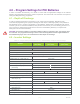
4.0 – Program Settings for PHI Batteries In order to maintain the Warranty, it is critical to ensure that the appropriate settings for the desired Warranty are programmed in all of the system components. This section will cover the basic concepts and settings for Magnum Energy equipment. 4.1 – Depth of Discharge In order to optimize performance and the life of your system and PHI batteries, SimpliPhi Power recommends programming the equipment settings for 80% Depth of Discharge (DoD).
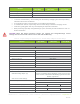
10k Cycles (80% DOD) General 5k Cycles (90% DOD) 09 Final Charge - Final 3.5k Cycles (100% DOD) Multi Rebulk (v) 25.3 / 50.6 10 Pwr Up Always - Pwr Up NO Notes: • • • • • 1. Per PHI 3.5 kWh battery – These setting are calculated by multiplying the nominal per-battery value times the number of batteries. 2. The maximum value of the low battery cut out (LBCO) is 24.4/48.8 V. 3. Calculate this value as a percentage of the inverter/charger’s maximum charging current.
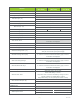
10k Cycles (80% DOD) General 5k Cycles (90% DOD) 02E AC In - SOC Disconnect SOC (%) 100 02F Power Up Always OFF 3.5k Cycles (100% DOD) 03 Charger Setup 45A per PHI3.5 24V 1 03A AC Input (A) 34A per PHI3.5 48V 03B VAC Dropout Set as applicable 03C Battery Type CC/CV 45A per PHI3.5 24V 1 Max Charge (A) 34A per PHI3.5 48V CV Charge (V) 28 / 56 CV Charge Done Amps DoneAmps (A) 4/2 MaxTime (Hrs) 12 Recharge (V) Time (Hrs) 25.3 / 50.
General 10k Cycles (80% DOD) 5k Cycles (90% DOD) 3.5k Cycles (100% DOD) 06 PT Setup 06A Battery Type CC/CV 45A per PHI3.5 24V 1 Max Charge (A) CV Charge (V) 34A per PHI3.5 48V 28 / 56 CV Charge Done Amps DoneAmps (A) 4/2 MaxTime (Hrs) 12 7 Recharge (V) Time (Hrs) 25.4 / 50.8 If “CC/CV” has been selected as battery type, “CC/CV Controlled” is displayed 0.1 Amps (A) 4/2 SOC (%) 100 06B Absorb Done 06C Max Charge Rate (%) 50 06D Max Charge Time (Hrs) 12 06E Bulk Start 25.4 / 50.
4.3 – MPPT Charge Controller Settings Solar charge controllers must be used in DC coupled systems to regulate the power produced by the PV array that is delivered to the batteries. Magnum Energy offers one MPPT charge controller, the PT-100, which is compatible with PHI batteries: The PT-100 model is somewhat unique in that allows for slightly larger strings of PV modules to be easily installed and connected to the PHI battery bank. See PV Input Voltages from pg. 17 of the PT-100 manual: Table 3.
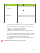
Parameters when DC is Connected 02G Inverter Threshold to Start Parallel 03 Charger Setup 03A AC Input Amps 03B Low VAC Dropout 03C Battery Type CC/CV Max Chg Amps CV Chg Volts CV Charge Done Time CV Charge Done Amps Hold CV Chg Volts 03D Absorb Done 03E Max Charge 03F Final Charge Stage 03G Days to remind when to EQ Setting 60% (default) Set to match the current rating of the utility power or the generator's circuit breaker. AC1 = 80, AC2 = 70 (default) 2-stage charging cycle 45 / 34 per battery 27.
Parameters 04I Gen No-Load Time 04J Gen 100% SOC Setting Consult your generator manufacturer for generator's Warm Up and Cooldown time. Not needed for LFP batteries. 05 BMK Setup 05A Charge Efficiency 05B Battery Amp Hrs Size 138 / 69 per battery 07 PT Setup 07A Battery Type CC/CV Max Chg Rate CV Chg Volts CV Charge Done Time CV Charge Done Amps Hold CV Chg Volts 07B Absorb Done 07C Max Charge 07D Bulk Start Daily/SunUp Low VDC SOC Two-stage charging cycle 45 / 34 per battery.
4.4 – Recharge or Rebulk Voltage Adjustment The recharge or rebulk setting often acts as the trigger in which a new charge cycle will start. The standard voltage set point is 50.5V, as per the manual; however you can adjust this setting to fit the application in which the battery is being used. The following table shows how battery voltage correlates to the state of charge. Table 7.0 – Correlating Battery Voltage to State of Charge SOC Voltage 48V Voltage 24V 100% >52.5 >26.2 95% 51.7 25.
5.0 – Specifications & Warranty For your reference: • • See PHI 3.5 kWh Specifications sheet. See PHI 3.5 kWh 10-Year Warranty; Failure to adhere to installation protocol will void Warranty. 6.0 – SimpliPhi Technical Support For technical support related to your PHI 3.5 kWh 48V Battery (or other SimpliPhi Power products), please contact us directly at: 805.640.1874 techsupport@simpliphipower.com SimpliPhi Power, Inc. | 3100 Camino Del Sol | Oxnard, CA 93030, USA | (805) 640-6700 | info@simpliphipower.