
SimpliPhi 1.3kWh Battery Install Manual

REV0402
18
SimpliPhi Power, Inc. | 420 Bryant Circle | Ojai, CA 93023, USA | (805) 640-6700 | info@simpliphipower.com | SimpliPhiPower.com
| 10 |
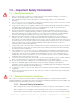
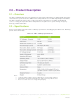
Considerations for Power Cable Terminations
Please factor in the below information for power cable terminations:
•
PHI 1.3 uses SB50 Anderson Connectors
o
12V connections are YELLOW
o
24V connections are RED
•
Power Cable Wire Gauge: Generally anywhere from 6 AWG to 2/0 AWG or larger
Protection from the Environment
To protect the positive and negative contacts, anticorrosive compounds or epoxies are
occasionally used in harsh or marine climate installations. Please contact your Electrician or
Qualified Installer to determine if this is advisable, and if so, what solution best suits your
application.
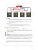
4.2.2 – Final Connection of the Installation
Final installation and operation guidelines will be dictated by your Electrician and Installer based
on the overall properties of and procedures for the equipment in your installation and any code
requirements that apply to your region. SimpliPhi Power, Inc. technicians and sales staff are
available to provide any additional information on the PHI 1.3 Battery as needed. Please contact
SimpliPhi Power for any technical support at your convenience. SimpliPhi Power, Inc. is
committed to providing safe, reliable energy storage and management that is maintenance free,
non-toxic and long-lasting. This commitment extends to our customers, valued installers,
partners, and to the community at large. Please be aware of the potential electrical hazards
before interacting with any and all electrical or mechanical devices. Please take all necessary
precautions in your projects and installations. Please refer to Section 1.0 above for safety
guidelines.
PHI 1.3 Batteries feature a Low Battery Voltage Cut Off (LBCO). This is a self-protection
mechanism that prevents over discharge. The LBCO will cause the PHI 1.3 Battery to turn off
once batteries approach Zero Capacity or 100% Depth of Discharge.
Most, if not all, inverters have related features. These features are often referred to as “Load
Disconnect”, “Load Shedding” or similar. These features are there to protect the PHI 1.3 Battery
bank from excessive discharge. In instances of low battery voltage, when there is no incoming
energy to recharge the PHI 1.3 Battery bank, the inverter will disconnect the load and remain in
standby until the PHI 1.3 Battery bank is recharged.
For off grid installations, where charge energy is only provided by renewable energy such as PV
arrays, Inverter “Load Disconnects” are generally set at a value that will allow a system to remain
online and in standby for at least 24 hours (10% at top of charge and 10% at bottom of charge).
This allows a system to stay online until at least one full day of sun can recharge the PHI 1.3
Battery bank.
In any application, off-grid or grid-tied, if your PHI 1.3 Battery bank is reaching the LBCO, load
disconnects, or load shedding set points may need to be adjusted. Refer to Programming section.
In case of LBCO, cycle the DC Battery Disconnect (inverter), in order to reset the system. Only
complete this procedure when there is a charge source available, otherwise, the system will
simply reach LBCO in a short time period and shut down again.