
PHI Series Battery Wiring Guide
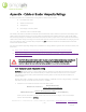
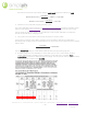
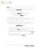
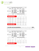
Table Of Contents
- SimpliPhi Wiring Guide
- 1.0 – Online Resources
- 2.0 – Technical Support
- 3.0 – General Safety Instructions
- 4.0 – Parallel Wiring
- 5.0 – PHI Battery Parallel Wiring Methods
- 6.0 – Cable or Busbar Ampacity Ratings
- PHI battery cable leads are typically sized at 4 AWG. This sizing is according to the battery’s 80ADC built-in breaker and therefore assumes a maximum current of 80 Amps flowing to or from an individual battery. While many other factors may be conside...
- 7.0 – Cable Wiring Batteries with Threaded Studs (Wiring Method #1)
- 8.0 – Busbar Connections for Batteries with Threaded Studs (Wiring Method #2)
- Example 1: Examine Figure 1.0 and consider both the maximum current liable to be drawn from the 4-PHI 3.8 kWh-48V battery bank instantaneously, as well as the maximum amount of current used to potentially charge the battery bank. Whichever value is gr...
- Assume: DC Loads = 0 Watts, Inverter AC Power Rating = 6,800 W, Inverter Charger Rating = 140 ADC, and MPPT Charge Controller Maximum Output = 60 ADC
- 1. Maximum current liable to be drawn from the battery bank
- 𝑀𝐴𝑋 𝐷𝐶 𝐶𝑢𝑟𝑟𝑒𝑛𝑡 𝐷𝑟𝑎𝑤=,𝑀𝐴𝑋 𝐷𝐶 𝑊𝑎𝑡𝑡 𝐷𝑟𝑎𝑤-𝐿𝑜𝑤𝑒𝑠𝑡 𝐵𝑎𝑡𝑡𝑒𝑟𝑦 𝐵𝑎𝑛𝑘 𝑉𝑜𝑙𝑡𝑎𝑔𝑒.
- 𝑀𝐴𝑋 𝐷𝐶 𝑊𝑎𝑡𝑡 𝐷𝑟𝑎𝑤=,𝐼𝑛𝑣𝑒𝑟𝑡𝑒𝑟 𝐴𝐶 𝑂𝑢𝑡𝑝𝑢𝑡 𝑃𝑜𝑤𝑒𝑟 𝑊𝑎𝑡𝑡𝑠-𝐼𝑛𝑣𝑒𝑟𝑡𝑒𝑟 𝐸𝑓𝑓𝑖𝑐𝑖𝑒𝑛𝑐𝑦.+,𝐷𝐶 𝐿𝑜𝑎𝑑 𝑊𝑎𝑡𝑡𝑠.
- Most systems have little to no DC Loads, and none are pictured in Figure 1.0. In this example, assume DC Load Watts = 0 WDC.
- Also assume Inverter AC Output Power Watts is 6,800 WAC and inverter efficiency is 93%.
- 𝑀𝐴𝑋 𝐷𝐶 𝑊𝑎𝑡𝑡 𝐷𝑟𝑎𝑤=,6,800 𝑊𝐴𝐶-0.93.+,0 𝑊𝐷𝐶.=7,312 𝑊𝐷𝐶
- 𝑀𝐴𝑋 𝐷𝐶 𝐶𝑢𝑟𝑟𝑒𝑛𝑡 𝐷𝑟𝑎𝑤=,7,312 𝑊𝐷𝐶-48 𝑉𝐷𝐶.=152.3 𝐴𝐷𝐶
- 2. Maximum current potentially charging the battery bank
- The Conext XW PRO inverter in Figure 1.0 (specification sheet linked here) includes a 140 ADC charger and the Conext MPPT charge controller in Figure 1.0 has a 60 ADC maximum charge current rating.
- Use the greater of these two numbers to conclude that, in this example, 140 ADC is the maximum amount of potential battery-charging current.
- 3. The greater of the two values is used to size the battery-to-inverter cables.
- In the Figure 1.0 example, 152.3 ADC is the larger of the two battery cable sizing considerations (discharging and charging amps), and should therefore be used to size the four positive and four negative battery cables:
- ,152.3 𝐴𝐷𝐶-4 𝐵𝑎𝑡𝑡𝑒𝑟𝑦 𝐶𝑎𝑏𝑙𝑒 𝑃𝑎𝑖𝑟𝑠.=38.083 𝐴𝐷𝐶
- Use the 38.083 ADC rating per set of battery cables to select the appropriate gauge wire.
- 4. Ampacity ratings may vary depending on which cable type you use. In this example, assume a THHN/THWN-2 (90 C insulation) copper conductor is used, and refer to the NEC’s Table 310.15(B)(16) to choose the AWG size cable accordingly. The four positiv...
- Example 2: Examine Figure 2.0 and assume the following in this example regarding the 12-PHI 3.8kWh-48V battery bank.
- Assume: DC Loads = 0 Watts, Two Conext XW+ 5548 inverters are used with AC Power Rating = 5,500 W each and efficiency of 93%, Inverter Charger Rating = 110 ADC per inverter, and two MPPT Charge Controllers are used each with Maximum Output = 80 ADC.
- 1. Maximum current liable to be drawn from the battery bank
- 𝑀𝐴𝑋 𝐷𝐶 𝑊𝑎𝑡𝑡 𝐷𝑟𝑎𝑤=,2×5,500 𝑊𝐴𝐶-0.93.+,0 𝑊𝐷𝐶.=11,828 𝑊𝐷𝐶
- 𝑀𝐴𝑋 𝐷𝐶 𝐶𝑢𝑟𝑟𝑒𝑛𝑡 𝐷𝑟𝑎𝑤=,11,828 𝑊𝐷𝐶-48 𝑉𝐷𝐶.=246.4 𝐴𝐷𝐶
- 2. Maximum current potentially charging the battery bank
- The Conext XW+5548 includes a 110A charger; two inverters in parallel have a combined charge rate of 220ADC. The two MPPT 80 charge controllers have a combined maximum output of only 160ADC, so the larger 220ADC figure is the maximum current potentia...
- 3. The greater of the two values is used to size the cables.
- Because 246.4 ADC is greater than 220ADC, the 246.4 ADC figure is used to size the battery cables. The battery cables from the battery combiner box to the inverters are sized according to the 246.4 ADC ampacity rating. From each individual battery to ...
- ,246.4 𝐴𝐷𝐶-12 𝐵𝑎𝑡𝑡𝑒𝑟𝑦 𝐶𝑎𝑏𝑙𝑒 𝑃𝑎𝑖𝑟𝑠.=20.53 𝐴𝐷𝐶
- 4. From these calculations, conclude that:
- The battery combiner box must be rated to 246.4 ADC or greater. Therefore, the MidNite Lithium Battery Combiner Box (link here), rated at 250 ADC, is appropriate.
- The twelve positive and twelve negative battery-to-combiner box cables are rated to handle at least 20.53 ADC. Refer to the NEC’s Table 310.15(B)(16) and in this example assume a THHN/THWN-2 (90 C insulation) copper conductor is used to choose a min...
- The single positive and single negative combiner box-to-inverters cables are rated to handle at least 246.4 ADC. Refer to the NEC’s Table 310.15(B)(16) and assume a THHN/THWN-2 (90 C insulation) copper conductor is used to choose a 4/0 AWG size cable.
- In Section 6.0 – Cabe or Busbar Ampacity Ratings of this Guide, battery cables are sized at 4AWG according to the battery’s 80ADC built-in breaker. As illustrated in previous examples of this Appendix, battery cables do not always need to be sized acc...
- Example 1: Examine Figure 4.0 (complete installation video linked here) and consider the busbar sizing required for the group of 3 PHI 3.4kWh-24V batteries. The paired inverter is a Magnum MS4024 rated at 4,000 Watts AC continuous output and 93% effic...
- 1. Maximum current liable to be drawn from the battery bank
- 𝑀𝐴𝑋 𝐷𝐶 𝑊𝑎𝑡𝑡 𝐷𝑟𝑎𝑤=,4,000 𝑊𝐴𝐶-0.93.+,0 𝑊𝐷𝐶.=4,301 𝑊
- 𝑀𝐴𝑋 𝐶𝑢𝑟𝑟𝑒𝑛𝑡 𝐷𝑟𝑎𝑤=,4,301 𝑊𝐷𝐶-24 𝑉𝐷𝐶.=179.2 𝐴𝐷𝐶
- 2. Maximum current potentially charging the battery bank
- The Magnum inverter includes a 105A charger. While the two charge controllers have a combined maximum charging output of 188 ADC. The greater of these two numbers – 188 ADC – is the maximum amount of potential battery-charging current.
- 3. The greater of the two values from Steps 1 and 2 is used to size the cables.
- 188 ADC, the maximum combined charging output of the two charge controllers, is the greater amount of current that is liable to energize the batteries’ interconnecting busbars and so the 188 ADC figure is used to size the battery busbars and cables.
- 4. From these calculations, conclude that:
- Each of the two three-battery busbars must be rated at least 188 ADC. SimpliPhi’s three-battery busbars (SKU #BB-3) with a 50 C rise are rated at 455 ADC, more than enough to handle the 188 ADC requirement.
- The single positive and single negative busbar-to-inverters cables are rated to handle at least 188 ADC. Refer to the NEC’s Table 310.15(B)(16) and assume a THHN/THWN-2 (90 C insulation) copper conductor is used to choose a 2/0 AWG size cable.
- Example 2: Examine Figure 5.0 and notice that the 6-PHI 3.8kWh-48V battery bank is arranged in two groups of three batteries, with busbars interconnecting each group of three batteries, and terminal blocks wired between the battery bank and the inverter.
- Assume: DC Loads = 0 Watts, one Sol-Ark-12K inverter’s AC Power Rating = 9,600 Watts, the inverter’s battery-to-AC output efficiency rating is 95.5%, the Sol-Ark-12K includes a built-in 185 ADC charger, and the connected solar PV array is rated at 12,...
- 1. Maximum current liable to be drawn from the battery bank
- 𝑀𝐴𝑋 𝐷𝐶 𝑊𝑎𝑡𝑡 𝐷𝑟𝑎𝑤=,9,600 𝑊𝐴𝐶-0.955.+,0 𝑊𝐷𝐶.=10,052 𝑊𝐷𝐶
- 𝑀𝐴𝑋 𝐷𝐶 𝐶𝑢𝑟𝑟𝑒𝑛𝑡 𝐷𝑟𝑎𝑤=,10,052 𝑊𝐷𝐶-48 𝑉𝐷𝐶.=209.4 𝐴𝐷𝐶
- 2. Maximum current potentially charging the battery bank
- The Sol-Ark-12K includes a 185A charger. In Sol-Ark’s combined (inverter and dual charge controller) unit, 185 ADC is the maximum charging current the equipment can use to charge the batteries, whether from an AC or DC power source.
- 3. The greater of the two values from Steps 1 and 2 is used to size the cables: 209.4 ADC.
- From each individual battery to the terminal blocks:
- ,209.4 𝐴𝐷𝐶-2 𝐵𝑎𝑡𝑡𝑒𝑟𝑦 𝐶𝑎𝑏𝑙𝑒 𝑆𝑡𝑟𝑖𝑛𝑔𝑠.=104.7 𝐴𝐷𝐶
- 4. From these calculations, conclude that:
- Each of the two terminal blocks (one positive, one negative) must be rated to 209.4 ADC or greater. Therefore, the 650 ADC-rated terminal blocks in the AccESS are acceptable. When choosing terminal blocks, also make sure that the blocks’ voltage rat...
- The single positive and single negative terminal block-to-inverter cables are also rated to handle at least 209.4 ADC. Refer to the NEC’s Table 310.15(B)(16) and assume a THHN/THWN-2 (90 C insulation) copper conductor is used to choose a 3/0 AWG or ...
- The two positive and two negative three-battery busbars must be rated to handle at least 104.7 ADC each. SimpliPhi’s three-battery busbars (SKU #BB-3) with a 50 C rise are rated at 455 ADC, more than enough to handle the 104.7 ADC requirement.
- The two positive and two negative busbar-to-terminal block cables are also rated to handle at least 104.7 ADC. Refer to the NEC’s Table 310.15(B)(16) and assume a THHN/THWN-2 (90 C insulation) copper conductor is used to choose a 3 AWG or greater si...

REV052720
SimpliPhi Power, Inc. | 3100 Camino Del Sol | Oxnard, CA 93030, USA | (805) 640-6700 | info@simpliphipower.com| SimpliPhiPower.com
| 16 |
The Sol-Ark-12K includes a 185A charger. In Sol-Ark’s combined (inverter and dual charge controller)
unit, 185 ADC is the maximum charging current the equipment can use to charge the batteries, whether
from an AC or DC power source.
3. The greater of the two values from Steps 1 and 2 is used to size the cables: 209.4 ADC.
From each individual battery to the terminal blocks:
209.4
2
= 104.7
4. From these calculations, conclude that:
• Each of the two terminal blocks (one positive, one negative) must be rated to 209.4 ADC or
greater. Therefore, the 650 ADC-rated terminal blocks in the AccESS are acceptable. When
choosing terminal blocks, also make sure that the blocks’ voltage rating is sized to handle the
paired PHI battery bank’s operating voltage (48V-56V, in this example).
• The single positive and single negative terminal block-to-inverter cables are also rated to handle
at least 209.4 ADC. Refer to the NEC’s Table 310.15(B)(16) and assume a THHN/THWN-2
(90°C insulation) copper conductor is used to choose a
3/0 AWG or greater size cable.
• The two positive and two negative three-battery busbars must be rated to handle at least 104.7
ADC each. SimpliPhi’s three-battery busbars (SKU #BB-3) with a 50°C rise are rated at 455
ADC, more than enough to handle the 104.7 ADC requirement.
• The two positive and two negative busbar-to-terminal block cables are also rated to handle at
least 104.7 ADC. Refer to the NEC’s Table 310.15(B)(16) and assume a THHN/THWN-2 (90°C
insulation) copper conductor is used to choose a
3 AWG or greater size cable.