
SimpliPhi AccESS Installation Manual


REV110619
SimpliPhi Power, Inc. | 3100 Camino Del Sol | Oxnard, CA 93030, USA | (805) 640-6700 | info@simpliphipower.com | SimpliPhiPower.com
| 38 |
Grid Setup Settings
The Sol-Ark’s Grid Setup menu includes many advanced features (refer to Section 5 of this Guide).
Regardless of the features used, the PHI battery bank should never discharge more than its maximum
continuous discharge rate. Furthermore, to maintain the PHI batteries’ Warranty at a 10,000-cycle level,
also do not discharge the battery bank to a State of Charge (SoC) level less than 20%. These details are
controlled in the Grid Setup menu’s Limiter tab.
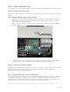
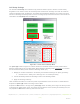
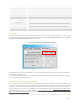
Figure 21.0 – Limiter Tab in Grid Setup Menu
The power (W) column in Figure 21.0 above dictates the maximum amount of power pulled from the
batteries and should be set to the PHI battery bank’s maximum discharge rate in AC Watts. To calculate
the connected PHI battery bank’s maximum discharge Watts (AC):
1. Multiply the number of batteries in the bank by the maximum discharge rate (ADC) per battery
a. PHI 3.8-51.2V
nom
battery max. discharge rate = 37.5 ADC per battery
2. Convert the battery bank’s DC discharge current to DC discharge watts.
3. Apply the discharge efficiency.
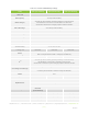
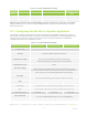
Table 3.0 below describes the continuous power output limitations of the PHI 51.2V
nom
-model batteries.
Populate the power (W) column according to these tables.
Populate the Batt column to the right of the power (W) column according to the degree to which you wish
to discharge the battery bank. Again, to maintain the PHI batteries at the 10,000-cycle Warranty level, do
not populate the Batt column with any value less than 20%.