Power. On Your Terms. SimpliPhi Sol-Ark AccESS INSTALLATION MANUAL INSTALLATION MANUAL Optimized Energy Storage & Management for Residential & Commercial Applications Utilizing Efficient, Safe, Non-Toxic, Energy Dense Lithium Ferrous Phosphate (LFP) Chemistry © SIMPLIPHI POWER, INC.
SimpliPhi Your Energy Security and Independence and gain control of your own power. SimpliPhi Power helps you manage your power as a personal resource. Anytime. Anywhere. SimpliPhi energy storage optimizes integration of any power generation source – solar, wind, generator – on or off grid and protects your home and mission-critical business functions from power outages and intermittency.
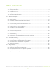
Table of Contents 1.0 – Important Safety Information .......................................................................................... 4 1.1 – Safety Instructions ......................................................................................................... 4 1.2 – Safety & Protective Features ......................................................................................... 5 1.3 – Limitations of Use ................................................................................
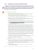
1.0 – Important Safety Information THE ACCESS UNIT AND PHI BATTERIES CONTAINED WITHIN THE UNIT MUST BE INSTALLED ACCORDING TO THE PROCEDURES OUTLINED IN THIS INSTALLATION MANUAL AND THE PHI BATTERY INSTALLATION MANUAL. ALL ACCESS UNIT OPERATION MUST BE IN ACCORDANCE WITH THE SETTINGS AND CONFIGURATION OUTLINED IN THIS MANUAL. FAILURE TO ADHERE TO EITHER THE ACCESS INSTALLATION MANUAL OR THE PHI BATTERY INSTALLATION MANUAL WILL VOID YOUR WARRANTY. 1.1 – Safety Instructions 1. 2. 3. 4. 5. 6. 7. 8. 9.
14. The AccESS unit does not have any user-serviceable parts. Do not disassemble the inverter except where noted for connecting wiring and cabling. See your Warranty for instructions on obtaining service. Attempting to service the components inside the AccESS unit yourself may result in a risk of electrical shock or fire and void the Warranty. Internal capacitors remain charged after all power is disconnected – wait 10 minutes before servicing. 15.
PHI batteries pose some risk of shock or sparking during the installation and initial wiring and connection process. This is consistent with all other battery-based storage formats. Be sure to turn the built-in circuit breaker to the “OFF” position to minimize the risk of shock or sparks during the installation and commissioning of the system. Use of insulated gloves, clothing and footwear is always recommended when working in close proximity to electrical devices.
1.2.4 – PHI 3.8 Battery Connection Terminals The PHI 3.8 batteries are equipped with two 3/8’’ threaded studs with a lock washer and nut. The red colored high temperature molded insert connection is for the positive lead. The black colored high temperature insert connection is for the negative lead. CAUTION: Do not attempt to loosen the large brass nut at the base of the terminals. This will void the Warranty. CAUTION: Do not reverse polarity. It will void the Warranty.
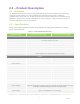
2.0 – Product Description 2.1 – Overview The SimpliPhi AccESS offers industry leading renewable energy storage technology to provides energy security and power resiliency into a pre-assembled, pre-programmed system that is suitable for installation inside and outside. The AccESS serves all of the common residential scale renewable energy applications: Off-Grid, Grid-Tied with Battery Back Up, Self Consumption – with Zero Export and Time Of Use (TOU) arbitrage for utility charge reduction. 2.
SPECIFICATIONS AccESS Sol-Ark-8K-15.2 kWh AccESS Sol-Ark-12K-22.8 kWh Solar PV DC Coupled Sol-Ark Dual MPPT 1 - 4 PV String Inputs (2 max per MPPT) 1 - 4 PV String Inputs (2 max per MPPT) Max Connected PV Power 11 kW (6 kW max per MPPT) 16.
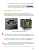
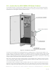
2.3 – Inside the AccESS NEMA-3R Rated Cabinet The AccESS system is enclosed within a NEMA-3R rated cabinet. Within, the internal layout provides easy access to clearly labeled wiring points and includes the necessary overcurrent devices, breakers and disconnects. See Figures 2.0 & 3.0 below for detail. Rain hood(s) optional Figure 2.0 – AccESS Unit Components The heart of the AccESS are the SimpliPhi Power PHI 3.8 kWh 51.2Vnom energy storage modules. The energy storage is modular and expandable.
monitoring (in the case of both AccESS Sol-Ark models) and remote system programming (in the case of the Sol-Ark-12K-22.8 kWh unit). 2.3.1 – AccESS Core Components The core components within the AccESS unit include the below listed products. See Figures 2.0 & 3.0 for detail.
3.0 – Pre-Installation The information within this section covers pre-installation procedures & considerations, namely, PHI 3.8 battery performance parameters to be aware of during the design process, guidance on system sizing, as well as installation site requirements and pad mounting. 3.1 – PHI 3.8 Battery Performance Parameters and Sizing Calculations The PHI 3.8 batteries within the Sol-Ark AccESS are designed to operate at a continuous discharge rate of 7.6 kWDC (AccESS Sol-Ark-8K-15.
3.3 – Installation Tools and Materials • • • • • Digital Multi Meter AC/DC Clamp-On Current Meter Wire Stripper Impact Driver Masonry Bolts 3.4 – Installation Site Location The AccESS may be installed indoors, such as a garage, or outdoors mounted onto a concrete pad. The cabinet is rated for NEMA-3R use. Please see Figure 3.0 below for physical AccESS dimensions, as this may impact the site location. Rain hood(s) optional Figure 3.0 – AccESS Unit Dimensions SimpliPhi Power, Inc.
3.5 – Clearance Requirements The AccESS should be installed with 3 inch (7.62 cm) clearance to the sides and 3 feet (0.91 m) clearance to the front to allow for the cabinet door to be opened during installation. Please see Figure 4.0 for details. All installations should comply with local code requirements and/or the local AHJ, which may exceed the requirements shown. Figure 4.0 – AccESS Unit Clearances SimpliPhi Power, Inc.
3.6 – Knock Out Locations Three 1.375-inch OD knockouts and one 2-inch OD knockout are located on both sides of the AccESS cabinet. They can be used for AC or DC inputs. Not all knockouts must be used. Figure 5.0 – AccESS Cabinet Knock-Outs (sides) 3.7 – Pad Mounting 3.7.1 – Pad Requirements The AccESS must be installed and secured on level concrete. For a pre-cast concrete pad, a 4” minimum thickness is required. The pad should be 3” wider than the AccESS on all sides (34” x 22” x 4”).
Figure 6.0 – AccESS Unit Knockouts (Bottom) SimpliPhi Power, Inc. | 3100 Camino Del Sol | Oxnard, CA 93030, USA | (805) 640-6700 | info@simpliphipower.com | SimpliPhiPower.
3.8 – Wire Run Lengths Two limiter sensors are included with the AccESS Sol-Ark. The limiter sensor wires are 10 feet long, and are extendable up to 50 feet using equipment from Sol-Ark (contact Sol-Ark directly at 972-575-8875; sales@sol-ark.com). Consider this distance when deciding the Sol-Ark AccESS unit’s location relative to the home’s main breaker panel. 3.
ark.com) for transfer switch kit purchase and installation instructions; It is not included in the AccESS Sol-Ark. 4.0 – Installation & Wiring This section covers how to install the PHI 3.8 batteries within the AccESS unit, torque values, communications and network preparation and how to wire the AccESS unit. It also provides guidance on how to install optional AccESS unit components/accessories. 4.
Figure 9.0 – Interconnecting Busbars Parallel the Batteries in Sets of Two 5. Secure the busbars to the batteries’ terminals using a 11/16” wrench socket to tighten the 3/8” lock washers and 11/16” stainless steel hex nuts (originally included on the batteries). Tighten the nuts to 160 in-lbs. Figure 10.0 – Interconnecting Busbars Secure to the Batteries’ Terminals 6. Connect the cables that are pre-wired into the Sol-Ark to the interconnecting busbars secured to the batteries.
AccESS Sol-Ark-12K-22.8 kWh model: 1. Mount the AccESS unit on level concrete. 2. Make sure all PHI battery module circuit breakers are in the OFF position. Prepare the battery modules for installation by removing all plastic terminal covers, 11/16” stainless steel hex nuts and 3/8” lock washers from the batteries’ terminals and set aside. CAUTION: Do not attempt to loosen the large brass nuts at the base of the battery terminals. 3. Place three PHI 3.
6. Connect the included 2/0 cables from the interconnecting busbars (secured to the batteries) to the 5-point terminal busbars. All connections are in parallel: each positive cable connects from each interconnecting positive busbar to the positive 5-point terminal busbar, and each negative cable connects from each negative busbar to the negative 5-point terminal busbar (refer to Figure 11.0 above). 7. Leave the PHI 3.8 batteries’ built-in breakers in the “OFF” position until the basic functional test.
4.5 – Wiring the AccESS 4.5.1 – Wiring Diagrams Please reference the below listed DC coupling and AC coupling diagrams, where applicable. DC Coupled System PV Array Connection To Batteries’ 5-Point Terminal Busbar (NEG) To Batteries’ 5-Point Terminal Busbar (POS) Figure 12.0 – DC Coupled AccESS Sol-Ark Wiring Diagram SimpliPhi Power, Inc. | 3100 Camino Del Sol | Oxnard, CA 93030, USA | (805) 640-6700 | info@simpliphipower.com | SimpliPhiPower.
AC Coupled System AC Coupled PV Array Connection To Batteries’ 5-Point Terminal Busbar (NEG) do not connect BTS To Batteries’ 5-Point Terminal Busbar (POS) no CAN Bus or RS485 connection Figure 13.0 – AC Coupled AccESS Sol-Ark Wiring Diagram SimpliPhi Power, Inc. | 3100 Camino Del Sol | Oxnard, CA 93030, USA | (805) 640-6700 | info@simpliphipower.com | SimpliPhiPower.
4.5.2 – Making AC Connections AC Landing Points – Terminal Blocks The AccESS is equipped with multiple knockouts on either side of the unit for accessibility to the Sol-Ark’s AC connections. All AC connections are rated at 120/240 VAC. The bi-directional grid port can also support two out of three phases of a 208 VAC grid connection (the two phases being L1 and L2, 120° out of phase).
Generator AC Wiring Generators wired to the Sol-Ark must be rated at 240VAC. Installations outside North America that incorporate generators rated at 230VAC / 50Hz can be wired to the Sol-Ark, provided there is no Neutral wiring connection. Generators can either be wired to the Sol-Ark’s Generator Input Port or to the Sol-Ark’s Bi-directional Grid Port. In grid-connected systems, generators cannot be wired to the Grid Port.
4.5.3 – AC System Bonding Multiple AC Neutral-to-Ground Bonds Verify that only one neutral-to-ground bond exists in the system. Having more than one neutral-to-ground bond in a system violates local electrical codes, may create a shock or fire hazard, and may cause some sensitive equipment to malfunction. The Sol-Ark’s neutral busbar accepts wire sizes up to 4 AWG. Failure to follow these instructions can result in death or serious injury and will void the Warranty.
Figure 16.0 - AccESS Cabinet Knockouts (Sides) 3. Strip 0.5” of insulation from the PV conductors, and insert into the appropriate charge controller port. Figure 17.0 - PV Array Connection Points (DC Coupled Systems) 4. Ground the solar PV array by panel frame grounding to any ground connection in the home using 12 AWG wire. Solar PV mounting structures typically bond frames together, so only one ground wire is needed. SimpliPhi Power, Inc.
AccESS Sol-Ark-8K-15.
• Eleven modules is the maximum allowable number of modules in series to prevent the solar PV string from exceeding the charge controller’s maximum voltage input rating even in the coldest weather conditions at the installation site: 500V ÷ 43.3V = 11.6 (round down to the next whole number). o Eleven modules in series at the KuPower 300W module’s VMP rating of 32.5V at STC also equates to 357.5V, well within the charge controller’s 150-425VDC maximum power point tracking range. 3.
AccESS Sol-Ark-12K-22.
in the coldest weather conditions at the installation site: 500V ÷ 43.3V = 11.6 (round down to the next whole number). o Eleven modules in series at the KuPower 300W module’s VMP rating of 32.5V at STC also equates to 357.5V, well within the charge controller’s 150-425VDC maximum power point tracking range. 3. The charge controller’s maximum short circuit current (I SC) input is 33ADC. Temperature also slightly affects the solar PV module’s current output: current increases as temperature increases.
4.5.5 – Limiter Sensor Wiring Connections The Sol-Ark AccESS installation may include limiter sensors. Limiter sensors are required in the following applications: • Limited to Home mode • Time of Use Selling mode • Systems that include both a generator and grid connection Install limiter sensors on incoming electrical service wires L1 and L2, at the top of the main house breaker panel (refer to Sol-Ark’s diagram on page 11 of the Sol-Ark-8K Manual).
4.5.6 – Basic Functional Test The following procedure should be followed once the installation is complete and before it is put into service. Step 1: Confirm All Connections After the AC and DC wiring has been installed and connected, check that all connections are correct and secure. Step 2: Apply Battery Power to the Inverter 1. Measure the voltage and check polarity at all battery connection points.
Step 5: Fully Charge the Battery Bank Prior to Powering On Loads A connection to an AC power source will result in the Sol-Ark automatically charging the batteries from that power source when the Sol-Ark is turned ON. If the system does not include any AC power source, and only solar PV as the batteries’ charging source, turn on the PV disconnect and wait until the PHI battery bank has had a chance to charge fully via solar power before turning on any loads.
5.0 – Programming 5.1 – Depth of Discharge The AccESS Sol-Ark comes pre-programmed for a maximum 80% depth of discharge (DoD) on the PHI batteries. This qualifies the batteries for the 10-year / 10,000 cycle Warranty. To change the batteries’ DoD to the 5,000-cycle Warranty or 3,500-cycle Warranty, modify the State of Charge (SoC) percentages as outlined in this Operating Parameters section of this Manual.
Table 2.0 – Sol-Ark AccESS Battery Settings System Setup > Battery Setup 80% DoD (10k cycle warranty) 90% DoD (5k cycle warranty) 100% DoD (3.5k cycle warranty) > Batt Tab Batt Capacity1 75 Ah per PHI 3.8 battery Max A Charge1,2 37.5 ADC per PHI 3.8 battery (20 ADC per battery for reduced stress) 80-150 ADC for 4 x PHI 3.8’s / 120-185 ADC for 6 x PHI 3.8’s* *The Sol-Ark’s maximum PV charging output is limited to 185 ADC. Max A Discharge1 37.5 ADC per PHI 3.
Batt Resistance Resistance mOhms = 96 ÷ (4 × PHI 3.8 battery quantity) Batt Charge Efficiency 99% > Smart Load Tab Use Gen input as load output check this box if the Smart Load feature applies (refer to Section 5 of this Guide) Smart Load OFF Batt8 95% (51.7 V) 100% (52.5 V) Smart Load ON Batt9 Wattage value is used in grid-connected systems only. This value represents the minimum power required of the solar array before the Smart Loads are powered.
Grid Setup Settings The Sol-Ark’s Grid Setup menu includes many advanced features (refer to Section 5 of this Guide). Regardless of the features used, the PHI battery bank should never discharge more than its maximum continuous discharge rate. Furthermore, to maintain the PHI batteries’ Warranty at a 10,000-cycle level, also do not discharge the battery bank to a State of Charge (SoC) level less than 20%. These details are controlled in the Grid Setup menu’s Limiter tab. Figure 21.
Table 3.0 – Sol-Ark AccESS Battery Settings A # of Parallel Batteries B C D E MAX Battery Output (WAC) DC Current Limit ADC X VDC (48) WDC X Discharge Efficiency (95%) 4 150 ADC 7,200 WDC 6,840 WAC 6,840 WAC 6 225 ADC 10,800 WDC 10,260 WAC 10,260 WAC Note: Sol-Ark’s Manual shows these power (W) parameters programmed to 1,000 Watts × PHI Battery Quantity. While there is no harm in using this approximation, the greater values outlined in the tables above may be used. 5.
CA Rule 21 check this box for compliance with CA Rule 21 UL 1741SA check this box for compliance with HECO Rule 14H and/or PREPA GEN connect to Grid input check this box when a generator is wired to the Grid Input > Grid Input Tab Grid Frequency Grid Type Protect Param > FreqVolt tab select 50 Hz or 60 Hz select 120/240V split phase (North America), or contact SimpliPhi to special-order 220V single phase or 120/208V 3 phase leave as default values when UL 1741 & IEEE 1547 are enabled frequency values
not exceed the maximum continuous discharge rate of the PHI battery bank. Refer to the Discharge Calculation in Section 3 of this Guide: 𝐼𝑛𝑣𝑘𝑊 ÷ 𝐼𝑛𝑣𝑒𝑓𝑓 𝐵#𝐼𝑛𝑣 ≥ 𝐵𝑎𝑡𝑘𝑊 Discharge Example: • Circuits on the essential loads sub-panel amount to a maximum potential power draw of 30 Amps at 240 VAC, or 7.2 kWAC • Sol-Ark-8K inverter DC-to-AC efficiency is 95.5% • PHI 3.8 kWh-51.2Vnom battery has a maximum continuous discharge rate of 1.92 kWDC 7.2𝑘𝑊 ÷ 0.955𝑒𝑓𝑓 = 3.9 1.
Time of Use Selling / Energy Arbitrage Discharge batteries to power circuits during specific set times. Program these times to coincide with the utility company’s peak pricing times to avoid high energy charges from the utility.
Off-Grid The Sol-Ark automatically operates in Off-Grid mode when it does not detect a grid connection. In an Off-Grid system setup, all the home’s loads are connected to the Sol-Ark’s Load Output (50A doublepole breaker). Do not use the Sol-Ark’s Grid Sell and Limited to Home modes in an off-grid system setup. Check the Limited power to load box in the Limiter tab of the Sol-Ark’s Grid Setup / Grid Param menu to allow for the batteries’ power to discharge to the connected loads.
In an AC Coupled system setup that includes a generator, using a transfer switch for a grid-or-generator connection to the Sol-Ark’s Grid Input also frees up the Sol-Ark Generator Input for connection to the AC Coupled solar PV array. If the system includes both a generator and a grid connection, limiter sensors are required.
Appendix A: Sol-Ark WiFi Setup Sol-Ark-8K Manual Excerpt SimpliPhi Power, Inc. | 3100 Camino Del Sol | Oxnard, CA 93030, USA | (805) 640-6700 | info@simpliphipower.com | SimpliPhiPower.
SimpliPhi Power, Inc. | 3100 Camino Del Sol | Oxnard, CA 93030, USA | (805) 640-6700 | info@simpliphipower.com | SimpliPhiPower.
SimpliPhi Power, Inc. | 3100 Camino Del Sol | Oxnard, CA 93030, USA | (805) 640-6700 | info@simpliphipower.com | SimpliPhiPower.
SimpliPhi Power, Inc. | 3100 Camino Del Sol | Oxnard, CA 93030, USA | (805) 640-6700 | info@simpliphipower.com | SimpliPhiPower.
Sol-Ark-12K Manual Excerpt (pg. 19-22) iPhone: https://apps.apple.com/us/app/powerview-es/id1460941008 Android: https://esem.cc/login SimpliPhi Power, Inc. | 3100 Camino Del Sol | Oxnard, CA 93030, USA | (805) 640-6700 | info@simpliphipower.com | SimpliPhiPower.
SimpliPhi Power, Inc. | 3100 Camino Del Sol | Oxnard, CA 93030, USA | (805) 640-6700 | info@simpliphipower.com | SimpliPhiPower.
SimpliPhi Power, Inc. | 3100 Camino Del Sol | Oxnard, CA 93030, USA | (805) 640-6700 | info@simpliphipower.com | SimpliPhiPower.
SimpliPhi Power, Inc. | 3100 Camino Del Sol | Oxnard, CA 93030, USA | (805) 640-6700 | info@simpliphipower.com | SimpliPhiPower.
SimpliPhi Power, Inc. | 3100 Camino Del Sol | Oxnard, CA 93030, USA | (805) 640-6700 | info@simpliphipower.com | SimpliPhiPower.
Appendix B: Rapid Shutdown Compliance Sol-Ark Manual Excerpt SimpliPhi Power, Inc. | 3100 Camino Del Sol | Oxnard, CA 93030, USA | (805) 640-6700 | info@simpliphipower.com | SimpliPhiPower.
SimpliPhi Power, Inc. | 3100 Camino Del Sol | Oxnard, CA 93030, USA | (805) 640-6700 | info@simpliphipower.com | SimpliPhiPower.