
AmpliPHI Sol-Ark Integration Guide
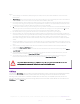
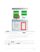
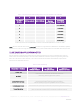
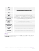
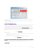
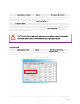
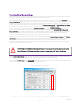
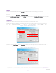
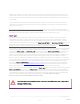
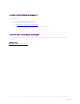
Table Of Contents
- 1. introduction
- 2. PHI battery bank-to-inverter connection
- Wire the PHI Battery bank to the Sol-Ark according to the PHI Battery Installation Manual, not according to the Sol-Ark Manual:
- Figure 1 – Sol-Ark to Battery Connection
- It is acceptable but not required to use the ferrite choke on the positive and negative DC busbar-to-inverter leads (see Figure 1 above).
- SimpliPhi and Sol-Ark recommend against using the 100 Ohm resistor included with the Sol-Ark equipment to charge the Sol-Ark’s capacitors when connecting the PHI Batteries for the first time (as described in the Sol-Ark Install Guide Owner’s Manual).
- Do not install the Battery Temperature Sensor. The PHI Batteries require no temperature compensation.
- 3. Battery bank sizing
- A properly sized PHI battery bank is sized to prevent over-discharge and over-charge from accompanying equipment. While the programming features of the Sol-Ark allow for battery discharging and charging according to specifically set parameters (refer ...
- Therefore, the PHI battery bank should still be sized to protect against over-discharge. In the case of an AC Coupled system setup, the PHI battery bank should also be sized to protect against over-charge from the solar photovoltaic (PV) array. In a D...
- Discharge Example: ,𝑩-#𝑰𝒏𝒗.≥,,𝑰𝒏𝒗-𝒌𝑾.÷,𝑰𝒏𝒗-𝒆𝒇𝒇.-,𝑩𝒂𝒕-𝒌𝑾..
- Charge Example: ,𝑩-#𝑷𝑽.≥,,𝑷𝑽-𝒌𝑾.-𝟎.𝟖×,𝑩𝒂𝒕-𝒌𝑾..
- AC Coupled Solar PV Array is rated at 8 kW
- PHI 3.8 kWh-51.2Vnom battery has a maximum continuous charge rate of 1.92 kWDC
- ,𝑩-#𝑷𝑽.≥,,𝟖-𝒌𝑾.-𝟎.𝟖×,𝟏.𝟗𝟐-𝒌𝑾..=𝟓.𝟐
- A properly sized PHI battery bank based on the maximum charge from the AC Coupled solar PV array has a minimum of 6 batteries. This ensures that the battery bank does not over-charge from the AC Coupled solar PV.
- When comparing the same system using both the discharge and charge calculations for sizing the PHI battery bank, the minimum number of batteries in the bank should be the greater of the two results. For instance, when examining the discharge calculati...
- While the PHI battery bank’s charge rate in a DC Coupled system can be limited via Sol-Ark programming (Max A Charge), consider the PHI battery bank’s maximum continuous charge rate in the system’s design.
- Charge Example: ,𝑩-#𝑷𝑽.≥,,𝑷𝑽-𝒌𝑾.×,𝑰𝒏𝒗-𝒆𝒇𝒇.-,𝑩𝒂𝒕-𝒌𝑾..
- DC Coupled Solar PV Array is rated at 8 kW
- Sol-Ark PV-to-Battery efficiency is 97.5%
- PHI 3.8 kWh-51.2Vnom battery has a maximum continuous charge rate of 1.92 kWDC
- ,𝑩-#𝑷𝑽.≥,,𝟖-𝒌𝑾.×,𝟎.𝟗𝟕𝟓-𝒆𝒇𝒇.-,𝟏.𝟗𝟐-𝒌𝑾..=𝟒.𝟎𝟔
- A PHI battery bank utilizing the entire DC Coupled solar PV output potential has 5 batteries. However, programming the Max A Charge in the Sol-Ark to 150 A (4 × 37.5 ADC) would prevent the over-charging of a battery bank that includes only 4 batteries...
- Homeowners with little to no loads on during the day (while solar power production is at its peak) might consider sizing a larger PHI battery bank to take advantage of the entire solar PV output potential for battery charging. Homeowners that consiste...
- 4. program settings for phi batteries
- 5. USE CASES & Application notes
- Sol-Ark equipment includes many advanced programming features and a variety of modes (more than one mode can be used simultaneously). This section of the Guide will outline the system programming and setup basics for common use cases. However, refer a...
- 6. SPECIFICATIONS & WARRANTY
- For your reference:
- See PHI 3.8 kWh Specifications Sheet.
- See PHI 2.9 kWh Specifications Sheet.
- See PHI Battery 10 Year Limited Warranty.
- Failure to adhere to installation protocol will void the Warranty.
- 7. SIMPLIPHI TECHNICAL SUPPORT
- For technical support related to your PHI Battery (or other SimpliPhi Power products), please contact us directly at:
- 805.640.6700
- techsupport@simpliphipower.com

REV
20201125
SimpliPhi Power, Inc. | 3100 Camino Del Sol | Oxnard, CA 93030, USA | (805) 640-6700 | info@simpliphipower.com | SimpliPhiPower.com
| 13 |
Time
sets the time at which the batteries discharge to power both the critical loads sub-panel
and the main house breaker panel (limiter sensors required)
power (W)
sets the maximum amount of power discharged from the batteries during the set time
do not exceed the Wattage values listed in Tables 2 or 3 above
Batt
the percentage SoC to which the batteries discharge during the set time
20% 10% 0%
Grid Charge
check this box to allow for grid-to-battery charging during the set time
GEN
check this box to allow for gen-to-battery charging during the set time
> Sell Control Tab
80% DoD
90% DoD
100% DoD
General Standard
check this box when a generator is wired to the Grid Input
or to use the
Protect Param
settings listed in the
Grid Input
tab
UL 1741 & IEEE 1547
check this box for grid sell compliant functionality (default)
CA Rule 21
check this box for compliance with CA Rule 21
UL 1741SA
check this box for compliance with HECO Rule 14H and/or PREPA
GEN connect to Grid input
check this box when a generator is wired to the Grid Input
> Grid Input Tab
Grid Frequency
select 50 Hz or 60 Hz
Grid Type
select 120/240V split phase (North America),
or contact SimpliPhi to special-order 220V single phase or 120/208V 3 phase
Protect Param
leave as default values when UL 1741 & IEEE 1547 are enabled
frequency values may change when a generator is wired to the Grid Input
> FreqVolt tab
refer to the Sol-Ark Manual for Puerto Rico or Kauai-specific settings
AC Coupled
In an AC Coupled system setup, the grid-tie inverter(s) output – string or micro-inverters – is wired to the Sol-
Ark’s Generator Input (40A double-pole breaker) and the
For Micro inverter input box in the Smart Load tab of
the
Battery Setup menu must be checked:
Figure 5 – Smart Load Tab in Batt Setup menu