
AmpliPHI Sol-Ark Integration Guide
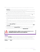
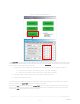
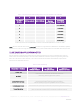
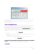
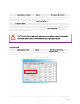
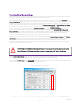
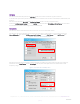
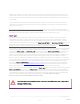
Table Of Contents
- 1. introduction
- 2. PHI battery bank-to-inverter connection
- Wire the PHI Battery bank to the Sol-Ark according to the PHI Battery Installation Manual, not according to the Sol-Ark Manual:
- Figure 1 – Sol-Ark to Battery Connection
- It is acceptable but not required to use the ferrite choke on the positive and negative DC busbar-to-inverter leads (see Figure 1 above).
- SimpliPhi and Sol-Ark recommend against using the 100 Ohm resistor included with the Sol-Ark equipment to charge the Sol-Ark’s capacitors when connecting the PHI Batteries for the first time (as described in the Sol-Ark Install Guide Owner’s Manual).
- Do not install the Battery Temperature Sensor. The PHI Batteries require no temperature compensation.
- 3. Battery bank sizing
- A properly sized PHI battery bank is sized to prevent over-discharge and over-charge from accompanying equipment. While the programming features of the Sol-Ark allow for battery discharging and charging according to specifically set parameters (refer ...
- Therefore, the PHI battery bank should still be sized to protect against over-discharge. In the case of an AC Coupled system setup, the PHI battery bank should also be sized to protect against over-charge from the solar photovoltaic (PV) array. In a D...
- Discharge Example: ,𝑩-#𝑰𝒏𝒗.≥,,𝑰𝒏𝒗-𝒌𝑾.÷,𝑰𝒏𝒗-𝒆𝒇𝒇.-,𝑩𝒂𝒕-𝒌𝑾..
- Charge Example: ,𝑩-#𝑷𝑽.≥,,𝑷𝑽-𝒌𝑾.-𝟎.𝟖×,𝑩𝒂𝒕-𝒌𝑾..
- AC Coupled Solar PV Array is rated at 8 kW
- PHI 3.8 kWh-51.2Vnom battery has a maximum continuous charge rate of 1.92 kWDC
- ,𝑩-#𝑷𝑽.≥,,𝟖-𝒌𝑾.-𝟎.𝟖×,𝟏.𝟗𝟐-𝒌𝑾..=𝟓.𝟐
- A properly sized PHI battery bank based on the maximum charge from the AC Coupled solar PV array has a minimum of 6 batteries. This ensures that the battery bank does not over-charge from the AC Coupled solar PV.
- When comparing the same system using both the discharge and charge calculations for sizing the PHI battery bank, the minimum number of batteries in the bank should be the greater of the two results. For instance, when examining the discharge calculati...
- While the PHI battery bank’s charge rate in a DC Coupled system can be limited via Sol-Ark programming (Max A Charge), consider the PHI battery bank’s maximum continuous charge rate in the system’s design.
- Charge Example: ,𝑩-#𝑷𝑽.≥,,𝑷𝑽-𝒌𝑾.×,𝑰𝒏𝒗-𝒆𝒇𝒇.-,𝑩𝒂𝒕-𝒌𝑾..
- DC Coupled Solar PV Array is rated at 8 kW
- Sol-Ark PV-to-Battery efficiency is 97.5%
- PHI 3.8 kWh-51.2Vnom battery has a maximum continuous charge rate of 1.92 kWDC
- ,𝑩-#𝑷𝑽.≥,,𝟖-𝒌𝑾.×,𝟎.𝟗𝟕𝟓-𝒆𝒇𝒇.-,𝟏.𝟗𝟐-𝒌𝑾..=𝟒.𝟎𝟔
- A PHI battery bank utilizing the entire DC Coupled solar PV output potential has 5 batteries. However, programming the Max A Charge in the Sol-Ark to 150 A (4 × 37.5 ADC) would prevent the over-charging of a battery bank that includes only 4 batteries...
- Homeowners with little to no loads on during the day (while solar power production is at its peak) might consider sizing a larger PHI battery bank to take advantage of the entire solar PV output potential for battery charging. Homeowners that consiste...
- 4. program settings for phi batteries
- 5. USE CASES & Application notes
- Sol-Ark equipment includes many advanced programming features and a variety of modes (more than one mode can be used simultaneously). This section of the Guide will outline the system programming and setup basics for common use cases. However, refer a...
- 6. SPECIFICATIONS & WARRANTY
- For your reference:
- See PHI 3.8 kWh Specifications Sheet.
- See PHI 2.9 kWh Specifications Sheet.
- See PHI Battery 10 Year Limited Warranty.
- Failure to adhere to installation protocol will void the Warranty.
- 7. SIMPLIPHI TECHNICAL SUPPORT
- For technical support related to your PHI Battery (or other SimpliPhi Power products), please contact us directly at:
- 805.640.6700
- techsupport@simpliphipower.com

REV
20201125
SimpliPhi Power, Inc. | 3100 Camino Del Sol | Oxnard, CA 93030, USA | (805) 640-6700 | info@simpliphipower.com | SimpliPhiPower.com
| 11 |
Figure 4 – Limiter Tab in Grid Setup menu
The power (W) column in Figure 4 above dictates the maximum amount of power pulled from the batteries and
should be set to
the PHI battery bank’s maximum discharge rate in AC Watts. To calculate the connected PHI
battery bank’s maximum discharge Watts (AC):
1. Multiply the number of batteries in the bank by the maximum discharge rate (ADC) per battery
a. PHI 3.8-51.2V
nom
battery max. discharge rate = 37.5 ADC per battery
b. PHI 2.9-51.2V
nom
battery max. discharge rate = 28.5 ADC per battery
2. Convert the battery bank’s DC discharge current to DC discharge watts.
3. Apply the discharge efficiency.
The following Tables 2 and 3 describe the continuous power output limitations of the PHI 51.2V
nom
-model
batteries. Populate the
power (W) column according to these tables.
Populate the Batt column to the right of the power (W) column according to the degree to which you wish to
discharge the battery bank. Again, to maintain the PHI batteries at the 10,000-cycle Warranty level, do not
populate the
Batt column with any value less than 20%.